Flue gas waste heat recovery system of large flue of sintering machine

A flue gas waste heat recovery system technology, applied in waste heat treatment, climate sustainability, lighting and heating equipment, etc., can solve problems such as large changes in working conditions, flue gas condensation, complex equipment systems, etc., to achieve convenient operation control , The effect of low operating cost and simple equipment

Inactive Publication Date: 2013-06-26
孙慕文
View PDF8 Cites 5 Cited by
  • Summary
  • Abstract
  • Description
  • Claims
  • Application Information

AI Technical Summary

Problems solved by technology

The existing patent CN201246965 adopts the technology of installing a waste heat boiler in the large flue to recover the waste heat of the flue gas. There are the following problems. First, the resistance on the large flue is increased, which has an impact on the sintering process; second, the equipment system is too complicated. Due to site restrictions, it is difficult to realize; 3. It is difficult to control the waste heat boiler, which may easily cause the temperature of the flue gas in the large flue to drop too much, resulting in the phenomenon of flue gas condensation, which will affect the sintering production; the patent ZL2011205458499 is only applicable to new sintering projects. When a damage accident occurs to the heat exchange device, it will affect the production of the main sintering process; patents CN201852474U and CN201858904U both use an external waste heat boiler to recover the flue gas from the large flue, and there are the following problems. First, the equipment system is complex and requires Adding a circulating fan will result in large investment and high energy consumption. Second, it occupies a large area. Third, it is difficult to control. Due to the poor stability of the sintering process and large changes in working conditions, it is easy to cause the adjustment of the waste heat boiler to fail to keep up. If there is too much heat, the temperature of the flue gas in the large flue will drop too much, and the phenomenon of flue gas condensation will occur, which will affect the production of sintering

Method used


Image

  • Flue gas waste heat recovery system of large flue of sintering machine
  • Flue gas waste heat recovery system of large flue of sintering machine

Examples


Embodiment 1

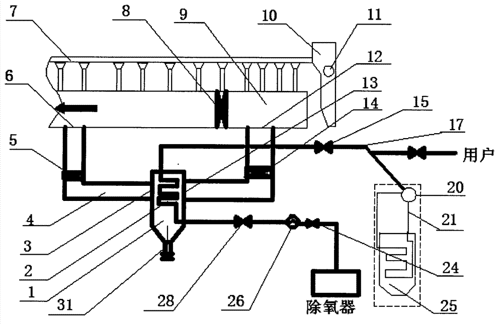
[0021] Such as figure 1 As shown, the sintering machine large flue flue gas waste heat recovery system of the present invention mainly includes a waste heat boiler (25), a heat exchanger (1), a sintering machine large flue (9), a sintering machine large flue control valve ( 8), the bypass flue (4) and deaerator of the large flue of the sintering machine; install the bypass flue (4) on the side of the large flue of the sintering machine (9), and install the bypass flue (4) on the side of the large flue of the sintering machine (9). ) is installed in the middle of the heat exchanger (1); the large flue control valve (8) is installed on the large flue (9) between the penultimate to the sixth air boxes at the tail of the sintering machine; the large flue control valve (8) is installed on the large flue control Between the valve (8) and the tail of the large flue (in the direction of the tail of the sintering machine), it connects the large flue (9) of the sintering machine with th...

Embodiment 2

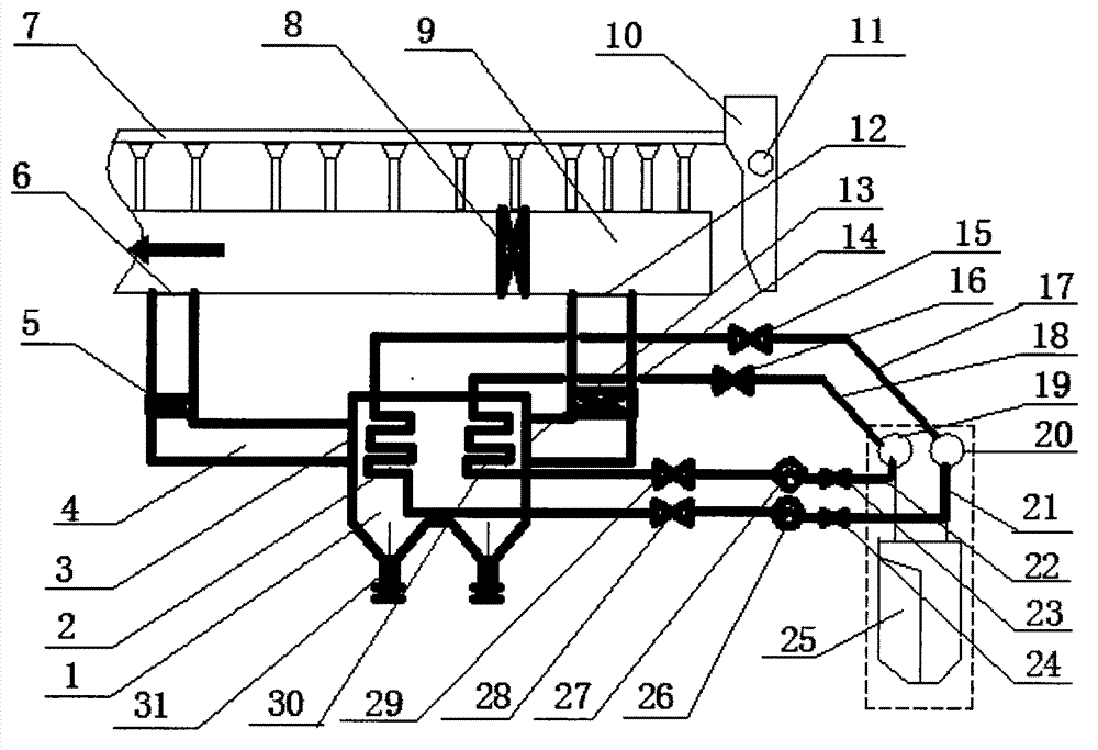
[0023] Such as figure 2As shown, the sintering machine large flue flue gas waste heat recovery system of the present invention mainly includes a waste heat boiler (25), a heat exchanger (1), a sintering machine large flue (9), and a sintering machine large flue control valve ( 8), the bypass flue (4) of the large flue of the sintering machine; press the bypass flue (4) on the side of the large flue (9) of the sintering machine, press the middle part of the bypass flue (4) Install a heat exchanger (1); install a large flue control valve (8) on the large flue (9) between the penultimate to the sixth wind boxes at the tail of the sintering machine; install a large flue control valve (8) on the large flue control valve (8) In the middle of the tail of the large flue (in the direction of the tail of the sintering machine), the large flue (9) of the sintering machine is connected with the bypass flue (4). At the flue (9), connect the large flue (9) with the bypass flue (4); betwee...


PUM


Abstract

The invention discloses a flue gas waste heat recovery system of a large flue of a sintering machine. The waste heat recovery system comprises a large flue near the tail of the sintering machine, wherein the large flue is internally provided with a valve, a bypass flue of the large flue is arranged near the large flue, the bypass flue is internally provided with a heat exchanger, the bypass flue between the heat exchanger and the large flue is provided with control valves, and the heat exchanger is provided with a water inlet pipe and a water outlet steam pipe. According to the invention, by controlling the amount of the flue gas of the large flue and the bypass flue, the flue gas heat amount of the large flue of the sintering machine can be adequately recovered, the lowest temperature of the flue gas of the large flue can be ensured as well, so that dew formation of flue gas can be avoided. The waste heat recovery system disclosed by the invention has the advantages of simple structure and controlling, economical investment, low operating cost, and is applicable to existing sintering systems and newly-built systems.

Description

technical field [0001] The invention relates to the field of recovery and utilization of sintering process waste heat, in particular to a method and equipment for efficiently recovering waste heat from a large flue of a sintering machine used in the sintering process of an iron and steel enterprise. Background technique [0002] In the process of iron and steel production, the energy consumption of the sintering process accounts for about 12% of the total energy consumption, ranking second only to the iron-making process. In the total energy consumption of the sintering process, the energy contained in the flue gas in the large tail flue of the sintering machine accounts for about 14% to 24% of the total energy consumption of the sintering process. Because the flue gas in the large flue at the tail of the sintering machine contains a large amount of sulfur dioxide, the heat of this part of the flue gas has not been effectively utilized at present. The existing patent CN2012...

Claims


Application Information

Patent Timeline
Patent Type & Authority Applications(China)
IPC IPC(8): F27D17/00F22B1/18
CPCY02P10/25Y02P80/15
Inventor 孙慕文
Owner 孙慕文
Why Eureka
Try Eureka