Interleaved parallel switch full-bridge inverter and interleaved parallel control method

A full-bridge inverter and switch technology, which is applied in the field of power electronic converters, can solve the problems of many switching tubes, heavy weight, and large volume of the staggered parallel inverter, so as to reduce the filter inductance, size, and size. The effect of a small input filter

Inactive Publication Date: 2013-06-26
SOUTHEAST UNIV
View PDF11 Cites 3 Cited by
  • Summary
  • Abstract
  • Description
  • Claims
  • Application Information

AI Technical Summary

Problems solved by technology

[0003] Purpose of the invention: In order to overcome the above existing problems and defects, the present invention proposes an interleaved parallel switch full-bridge inverter and an interleaved parallel control method, which solves the problem that the existing interleaved parallel inverter is large in size, heavy in weight, and the switching tube many questions

Method used


Image

  • Interleaved parallel switch full-bridge inverter and interleaved parallel control method
  • Interleaved parallel switch full-bridge inverter and interleaved parallel control method
  • Interleaved parallel switch full-bridge inverter and interleaved parallel control method

Examples


Embodiment 1

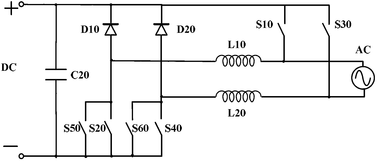
[0024] Such as figure 2 As shown, the interleaved parallel switch full-bridge inverter of the present invention receives the input DC voltage DC from the solar cell, and outputs the AC power to the AC grid AC, including: an input capacitor C20, whose positive pole is connected to the positive input of the input DC power supply DC end, its negative pole is connected to the ground potential of the input direct current power supply DC; the first diode D10, its cathode is connected to the positive pole of the input capacitor C20, its anode is connected to the first end of the first inductor L10, the first inductor L10 The second terminal of the second diode is connected to the first input terminal of the alternating current network AC; the second diode D2, its cathode is connected to the positive pole of the input capacitor C20, its anode is connected to the first terminal of the second inductor L20, the second inductor The second end of L20 is connected to the second input end o...

Embodiment 2

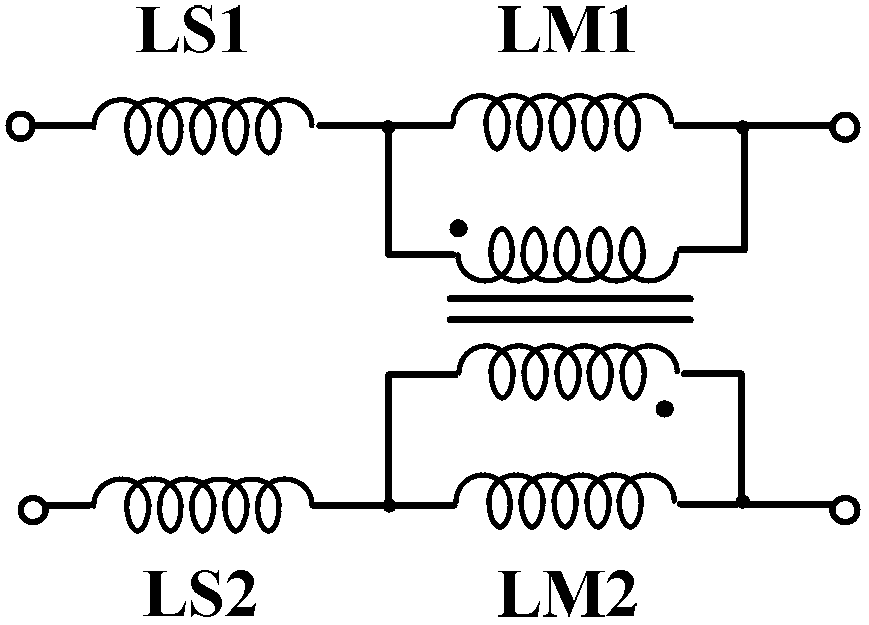
[0027] Such as image 3 As shown, in this embodiment, another embodiment of the first inductor and the second inductor of the full-bridge inverter with interleaved parallel switches, the first inductor L10 includes the first leakage inductance LS1 and the first magnetizing inductance connected in series LM1, the second inductor L20 includes a second leakage inductance LS2 and a second magnetizing inductance LM2 connected in series, the first leakage inductance LS1, the second leakage inductance LS2, the first magnetizing inductance LM1 and the second magnetizing inductance LM2 share a magnetic core The first magnetizing inductor LM1 and the second magnetizing inductor LM2 are differentially coupled, preferably, the first magnetizing inductor LM1 and the second magnetizing inductor LM2 have the same inductance value.

Embodiment 3

[0029] Such as Figure 4 As shown, in this embodiment, another embodiment of the first inductor and the second inductor of the full-bridge inverter with interleaved parallel switches, the first inductor L10 includes the first magnetizing inductance LM1 and the third magnetizing inductance LM3 connected in series , the second inductor L20 includes a second magnetizing inductor LM2 and a fourth magnetizing inductor LM4 connected in series, the first magnetizing inductor LM1, the second magnetizing inductor LM2, the third magnetizing inductor LM3 and the fourth magnetizing inductor LM4 share a magnetic core, The first magnetizing inductor LM1 is differentially coupled to the second magnetizing inductor LM2, and the third magnetizing inductor LM3 is coupled to the fourth magnetizing inductor LM4 in common mode. Preferably, the inductance values ​​of the first magnetizing inductor LM1 and the second magnetizing inductor LM2 are the same. The inductance values ​​of the third magneti...


PUM


Abstract

The invention discloses an interleaved parallel switch full-bridge inverter and an interleaved parallel control method. The interleaved parallel switch full-bridge inverter comprises an input capacitor, a first diode, a second diode, a first switch tube, a second switch tube, a third switch tube, a fourth switch tube, a fifth switch tube, a sixth switch tube, a first inductor and a second inductor. The inverter has the advantage that size and weight of the inductors are reduced, and quantity of the switch tubes is decreased; the problems of reverse recovery of the diodes and the like are avoided, and efficiency and reliability are improved; common-mode voltage between a direct-current bus and an alternating-current bus is mainly low-frequency variable voltage to be beneficial to reducing of size of an EMI (electro-magnetic interference) filter; when sizes of output inductive current ripples are same, switch interleaving is beneficial to reducing of output filter inductance, so that input current is continuous, and input filters are decreased; and coupling inductance is conducive to inductance multiplexing to further reduce filter inductance.

Description

technical field [0001] The invention relates to the field of power electronic converters, in particular to a grid-connected inverter. Background technique [0002] The grid-connected inverter is a bridge between solar cells and the grid, which is related to the level of photoelectric conversion efficiency. In order to increase the output power of grid-connected inverters, the way of interleaved parallel connection is usually adopted, such as figure 1 As shown, the solar battery DC provides direct current energy converted from solar energy, and the diode D1, diode D2, switching tube S1, switching tube S2, switching tube S3, switching tube S4, inductor L1 and inductor L2 constitute the first inverter Circuit, diode D3, diode D4, switch tube S5, switch tube S6, switch tube S7, switch tube S8, inductor L3 and inductor L4 constitute the second inverter circuit, the first inverter circuit and the second inverter circuit They are interleaved and connected in parallel to jointly p...

Claims


Application Information

Patent Timeline
Patent Type & Authority Applications(China)
IPC IPC(8): H02M7/5387
Inventor 嵇保健王建华赵剑锋
Owner SOUTHEAST UNIV
Why Eureka
Try Eureka