High-power automobile rectifier bridge soldering method and lug thereof

A welding method and rectifier bridge technology, which are applied in output power conversion devices, welding equipment, resistance welding equipment, etc., can solve the problem that the welding method of high-power vehicle rectifier bridges is not ideal, reduces the service life of diode chips, and occupies assembly space, etc. problem, to achieve the effect of simple structure, saving raw materials and reducing volume

Active Publication Date: 2013-07-03
GUIZHOU YAGUANG ELECTRONICS TECH
View PDF9 Cites 2 Cited by
  • Summary
  • Abstract
  • Description
  • Claims
  • Application Information

AI Technical Summary

Problems solved by technology

[0002] At present, when making high-power vehicle rectifier bridges, the welding ends of the lugs on the high-power vehicle rectifier bridges often adopt the U-shaped card structure. During welding, the lead wire of the diode is first embedded on the U-shaped clip-type welding end of the lug, and then welded. Using the lug of this structure for welding, there are mainly the following problems: 1. 1. Due to the large volume of the welding end, a large solder joint is formed after welding, which not only wastes raw materials, but also takes up assembly space; 2. The existing lug structure must use a welding tool with a higher temperature For welding, in the existing technology, argon arc welding is often used for welding, and the principle of argon arc welding is that the argon arc welding machine generates a high-frequency oscillating voltage (about 3000V), using thoriated tungsten or cerium tungsten rods as electrodes, and the tip discharges, Break down the air, generate an arc between the welding points, use the contact resistance at the welding point to generate high temperature for melting welding, because the actual position of the argon arc welding head has certain uncertainty, if there is a wrong arc with the metal parts on the rectifier bridge phenomenon, the corresponding main rectifier diode will be energized, which will cause great damage to the diode, and sometimes even cause the diode to fail
3. Due to the large volume of the welding end, the temperature is high during welding. The high temperature generated by welding will cause great damage to the diode chip and greatly reduce the service life of the diode chip.
Due to the above problems, the welding method of the existing high-power vehicle rectifier bridge is still not ideal.

Method used


Image

  • High-power automobile rectifier bridge soldering method and lug thereof
  • High-power automobile rectifier bridge soldering method and lug thereof

Examples


Embodiment Construction

[0011] The present invention will be further described below in conjunction with the accompanying drawings and embodiments, but not as a basis for limiting the present invention.

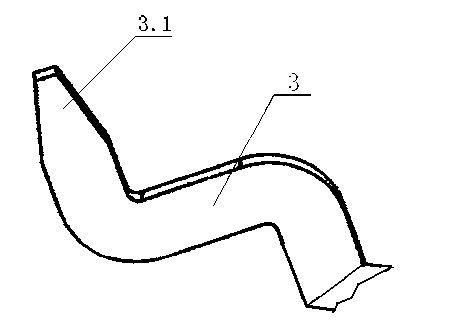
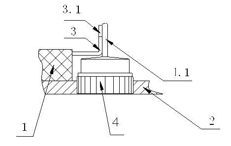
[0012] Embodiment of the present invention: the welding method of a kind of high-power vehicle rectifier bridge of the present invention can be implemented on the production line of existing high-power vehicle rectifier bridge, during implementation, existing diode 4 is pressed traditional When the rectifier circuit connection method is welded to form a high-power vehicle rectifier bridge, the base of the diode 4 is first embedded on the pole plate 2 of the rectifier bridge, and the pole plate 2 is riveted and fixed on the insulating bracket 1 of the rectifier bridge, and the insulating bracket 1, next to each diode 4 is fixed a lug 3 for forming a high-power vehicle rectifier bridge after being welded with the lead wire of the diode, and the welding end 3.1 at the front end of the lug 3 is made i...


PUM


Abstract

The invention discloses a high-power automobile rectifier bridge soldering method and a lug thereof. When diodes need to be soldered according to the conventional rectifier circuit connection method to form a high-power automobile rectifier bridge, the bases of the diodes are first fixedly embedded in a polar plate of the rectifier bridge, the polar plate is fixed on an insulating support of the rectifier bridge, lugs which are used for being soldered on the leads of the diodes to jointly form the high-power automobile rectifier bridge are respectively fixed beside each diode on the insulating support, the front soldering end of each lug is produced into the shape of a flat arrowhead, the butt-soldering method is then adopted to respectively solder the leads of the diodes on the soldering ends of the lugs fixed on the support, and thereby the high-power automobile rectifier bridge is formed. The invention not only has the advantages of lower soldering temperature and high product quality, but also has the advantages of simple structure, low production cost, small solder joints, material saving, high finished product rate and the like.

Description

technical field [0001] The invention relates to a welding method for a high-power vehicle rectifier bridge and its lugs, belonging to the technical field of rectifier bridge manufacture. Background technique [0002] At present, when making a high-power vehicle rectifier bridge, the welding end of the lug on the high-power vehicle rectifier bridge often adopts a U-shaped card structure. When welding, the lead wire of the diode is first embedded in the U of the lug After the welding end of the card type is put on, then welding is carried out, and the welding lug of the existing structure mainly has the following problems: 1. Due to the large volume of the welding end, a large gap is formed after welding. This not only wastes raw materials, but also takes up assembly space; 2. The existing lug structure must be welded with a welding tool with a higher temperature. In the prior art, argon arc welding is often used for welding. The principle of argon arc welding is that the arg...

Claims


Application Information

Patent Timeline
Patent Type & Authority Applications(China)
IPC IPC(8): B23K11/02H01L23/488H02M1/00
Inventor 杨华李勇林立志皮昆鹏陈国辉
Owner GUIZHOU YAGUANG ELECTRONICS TECH
Why Eureka
Try Eureka