Method for manufacturing aluminum pot used by special mold for gravity cast energy-saving aluminum pot

A technology of gravity casting and manufacturing method, applied in the direction of manufacturing tools, casting and molding equipment, applications, etc., can solve the problems of insufficient riveting force of iron plate aluminum, complicated procedures, and complicated processing, and achieve simple processing methods, fast and uniform heat transfer, large area effect

Active Publication Date: 2015-05-20
福建鼎厨王厨具有限公司
View PDF7 Cites 3 Cited by
  • Summary
  • Abstract
  • Description
  • Claims
  • Application Information

AI Technical Summary

Problems solved by technology

This cold stamping production method has the following disadvantages: First, the production method is cumbersome, the aluminum pot and the iron plate cannot be integrally formed, and the two need to be processed separately and then combined and fixed by a high-tonnage stamping machine
The equipment requirements are high, usually the stamping machine should be more than 800-2000 tons. Second: through cold stamping, the aluminum metal is hard squeezed into the iron plate turning hole, and the extrusion force is uneven, and the fullness of the turning aluminum metal is uneven. Poor precision, prone to gaps, such as Figure 1A As shown, water vapor is easy to infiltrate from this gap during use, resulting in noise and easy iron plate detachment
Third; due to insufficient aluminum riveting force of the iron plate, the steel plate is easily deformed after passing through high temperature during use, resulting in uneven bottom of the whole pot and uneven heating during use. Fourth; iron plate and aluminum metal riveting at the bottom of the pot body The resultant force is limited, and the bottom finishing can no longer be done. The appearance is limited and the beauty is not enough.
[0004] The above cold stamping manufacturing method is to forcibly deform the aluminum metal material and then insert it on the stainless steel plate. Easy to fall off, not long service life, etc.
[0005] In view of the shortcomings of the cold working method adopted above, Chinese Invention Patent Application Publication No. (CN1846577A) and (CN10554287) disclose a cast aluminum cooker that can be used in an induction cooker and a manufacturing method thereof. The iron plate is poured into the chassis of the pot and cooker. It can be formed at one time during processing without recombining the iron plate. However, the processing technology of the former is that the aluminum liquid completely wraps the flat steel plate in it, and only the edge of the iron plate is exposed. The outer bottom surface of the bottom is easy to form The following deficiencies: First, the coefficients of thermal expansion and contraction of the two materials are different, and gaps are likely to occur between the cracks, and similar gaps will also occur at the edge of the hole and the aluminum joint, such as Figure 1B As shown, since there are few riveting points between the iron plate and aluminum, the iron plate is easy to warp during use, resulting in uneven bottom, which affects the heating uniformity and service life
The latter processing technology is to insert the flat iron plate in the middle of the aluminum material, the aluminum liquid exceeds the iron plate to form ribs, and wraps the edge of the iron plate within the edge, which is easy to cause the following problems. First, the iron plate is easy to deviate, so that the iron plate and the aluminum There are gaps between them, and water vapor can easily penetrate into the bottom iron plate. Secondly, because the flat iron plate is easily deformed during the pouring process, it needs to be reshaped by a large punching machine and then reshaped for correction, resulting in cumbersome processing technology. , the process is complicated, the casting process is difficult, the production cost is high, and the ribs formed by the aluminum liquid are stepped, and the area of ​​the aluminum ribs is more than the exposed iron plate area, resulting in low magnetic flux power and slow heating speed. Figure 1C shown

Method used


Image

  • Method for manufacturing aluminum pot used by special mold for gravity cast energy-saving aluminum pot
  • Method for manufacturing aluminum pot used by special mold for gravity cast energy-saving aluminum pot
  • Method for manufacturing aluminum pot used by special mold for gravity cast energy-saving aluminum pot

Examples


Embodiment Construction

[0032] The present invention will be further described below in conjunction with the accompanying drawings.

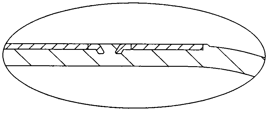
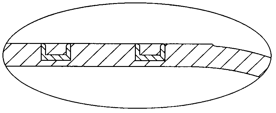
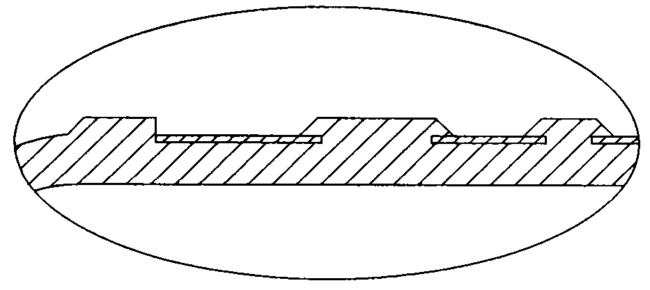
[0033] Such as Figure 2A , Figure 2B , Figure 2C , image 3 and Figure 4 As shown, what the present invention relates to is a method for manufacturing an energy-saving aluminum pan for a gravity casting induction cooker, which is characterized in that it comprises the following steps:

[0034] One, preparation is cast on the stainless iron plate at the bottom of the pan, see Figure 2A shown

[0035] Because the flat stainless iron plate is easily deformed in high temperature heating, in order to achieve the above purpose, the invention adopts a special three-dimensional stainless iron plate, and presses the inner and outer diameters of the whole stainless iron plate into a three-dimensional Z-line shape, so that the inside and outside form a three-dimensional shape. Tensile force, the inner diameter of the stainless steel plate is pressed into equal four-equ...


PUM


Abstract

The invention discloses a gravity cast method for an energy-saving aluminum pot for an induction cooker. The method comprises the steps of preparing a stainless iron plate cast at the bottom of the pot; preparing a special mold matched with the stainless iron plate; and performing gravity casting, wherein the gravity casting comprises a molding process of a pot body and the stainless iron plate, rivet processing at the outer bottom of the pot and processing of the shrinkage cavity surface of a casting surface. According to the gravity cast method and a special mold for the gravity cast energy-saving aluminum pot for the induction cooker, the stainless iron plate and the pot body can be cast integrally; and the heat conduction is uniform, the electromagnetic power is high, energy is saved, and the pot bottom and the stainless iron plate can be combined precisely during usage, so that deformation and falling are prevented.

Description

technical field [0001] The invention relates to a manufacturing method of an energy-saving aluminum pot for gravity casting induction cooker, especially an energy-saving pot with an aluminum pot bottom and a stainless iron plate integrally formed, which can be used in an electromagnetic cooker and various stoves. gravity casting method. Background technique [0002] Generally, pots for induction cookers are suitable for iron pots and stainless steel pots. Aluminum pots cannot use induction cookers to conduct heat. This is because aluminum has no magnetic conductivity and must be installed with stainless iron plates. The coefficients of expansion and contraction are different, and the deformation of aluminum and stainless iron plates is different when heated, which will lead to deformation of the stainless iron plate, and seriously cause the entire stainless iron plate to fall off from the pot body. [0003] Aiming at the above-mentioned deficiencies, the solution of the exi...

Claims


Application Information

Patent Timeline
Patent Type & Authority Patents(China)
IPC IPC(8): B22D19/16B22C9/22A47J27/00
Inventor 周聪明
Owner 福建鼎厨王厨具有限公司
Why Eureka
Try Eureka