
Plasma treatment device and plasma treatment method for polymer material surface modification

A polymer material and plasma technology, applied in the direction of ultrasonic/sonic fiber treatment, etc., can solve the problems of uneven quality of polymer surface modification, difficulty in making radio frequency or microwave power supply, and difficult to achieve stable discharge, so as to avoid burning Erosion piercing and thermal damage, wettability improvement, moderate temperature and energy effects

Active Publication Date: 2013-07-10
CHONGQING UNIV OF POSTS & TELECOMM
View PDF3 Cites 14 Cited by
  • Summary
  • Abstract
  • Description
  • Claims
  • Application Information

AI Technical Summary

Problems solved by technology

[0008] The Chinese patent with the publication number CN1900408 discloses a corona discharge low-temperature plasma fabric modification treatment device. Although the device can achieve the purpose of fabric modification under normal pressure to a certain extent, there are A large number of filament discharges with high energy density, which will cause damage to the polymer surface and cause uneven quality of polymer surface modification
[0009] In the same way, the Chinese patent with publication number CN101580594 discloses a method for modifying the interface of aramid fiber composite materials by dielectric barrier discharge plasma technology. Defects that cause damage to the surface of the object and cause uneven quality of polymer surface modification
[0010] In addition, the current atmospheric pressure discharge plasma is usually generated by radio frequency or microwave capacitive coupling or inductive coupling discharge. High-power radio frequency or microwave power supply is difficult to manufacture, the price is high, and it is easy to interfere with the human body and other measuring equipment. Power-driven discharge plasma is not easy to achieve a stable discharge due to the easy transition from glow to arc

Method used


Image

  • Plasma treatment device and plasma treatment method for polymer material surface modification
  • Plasma treatment device and plasma treatment method for polymer material surface modification
  • Plasma treatment device and plasma treatment method for polymer material surface modification

Examples


no. 1 example

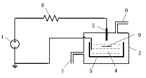
[0040] Such as figure 1 Shown is a schematic structural view of an embodiment of a plasma treatment device for surface modification of polymer materials according to the present invention. The plasma treatment device used in this embodiment for surface modification of polymer materials includes a DC power supply 1 and a reaction chamber 2. The reaction chamber 2 is correspondingly provided with a metal anode 3 and a liquid cathode 4 connected to the DC power supply 1 respectively, and the reaction The chamber 2 is provided with a container 5 for containing the liquid medium of the liquid cathode 4, and the metal anode 3 is arranged directly above the liquid surface of the liquid cathode 4, and the reaction chamber 2 is also provided with an air intake system for the circulation of the gas medium.

[0041]Preferably, the reaction chamber 2 of this embodiment is provided with an adjustment device for adjusting the distance between the metal anode 3 and the liquid cathode 4, and ...

no. 2 example

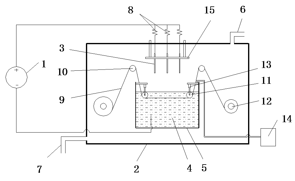
[0048] Such as figure 2 Shown is a schematic structural view of the second embodiment of the plasma treatment device for surface modification of polymer materials according to the present invention. The plasma treatment device used in this embodiment for surface modification of polymer materials includes a DC power supply 1 and a reaction chamber 2. The reaction chamber 2 is correspondingly provided with a metal anode 3 and a liquid cathode 4 connected to the DC power supply 1 respectively, and the reaction The chamber 2 is provided with a container 5 for containing the liquid medium of the liquid cathode 4, and the metal anode 3 is arranged directly above the liquid surface of the liquid cathode 4, and the reaction chamber 2 is also provided with an air intake system for the circulation of the gas medium.

[0049] In this embodiment, the reaction chamber 2 is provided with a driving device for continuous feeding of the polymer material. The driving device includes a driving ...


PUM


Abstract

The invention discloses a plasma treatment device for polymer material surface modification. The plasma treatment device comprises a direct-current power supply and a reaction chamber, wherein a metal anode and a liquid cathode which are connected with the direct-current power supply are arranged in the reaction chamber correspondingly; a liquid-medium container used for containing the liquid cathode is arranged in the reaction chamber; the metal anode is arranged right above a liquid level of the liquid cathode; and the reaction chamber is internally provided with a gas inlet system for circulating gas media. The invention further discloses a plasma treatment method for the polymer material surface modification. The plasma treatment method comprises the following steps of 1) placing a polymer material to be treated below the liquid level of the liquid cathode; 2) starting the gas inlet system to conduct gas inlet on the reaction chamber; 3) turning on the direct-current power supply, adjusting a space between the metal anode and the liquid cathode to allow discharge plasma to generate between the metal anode and the liquid cathode, and beginning to conduct plasma treatment on the polymer material; and 4) turning off the direct-current power supply after the treatment, and taking out the polymer material.

Description

technical field [0001] The invention relates to a device and method for surface modification of polymer materials, in particular to a device and method for improving the surface properties of polymer materials by using low-temperature plasma generated by glow discharge under atmospheric pressure. Background technique [0002] Polymer materials are widely used in all aspects of industrial production and people's daily life because of their excellent mechanical properties, chemical properties and thermal stability. However, due to the low hydrophilicity of the polymer surface, it is difficult to bond with other materials, so it is necessary to improve its surface properties. [0003] At present, the methods widely used in polymer surface modification include chemical treatment, photoirradiation treatment and plasma treatment, etc. Among them, plasma treatment has attracted more and more attention because of its non-pollution to the environment. Atmospheric pressure glow disch...

Claims


Application Information

Patent Timeline
Patent Type & Authority Applications(China)
IPC IPC(8): C08J7/12D06M10/02
Inventor 郑培超刘克铭王金梅代玉于斌
Owner CHONGQING UNIV OF POSTS & TELECOMM
Learn More