Circularly polarized antenna array having spinning characteristic in space structure

A technology of circularly polarized antennas and space structures, which is applied to antenna unit combinations with different polarization directions and structural forms of radiating elements. Simple, Small Effects

Inactive Publication Date: 2013-07-24
LINGBAYI ELECTRONICS GRP
View PDF2 Cites 15 Cited by
  • Summary
  • Abstract
  • Description
  • Claims
  • Application Information

AI Technical Summary

Problems solved by technology

[0008] The task of the present invention is to provide a circularly polarized antenna array composed of metal cross pendant dipole antenna units, which can cancel the cross-polarized component and realize a relatively low frequency when the result is not ideal after the formation of the array and it is difficult to achieve circular polarization. Circularly polarized antenna array with good circularly polarized radiation performance

Method used


Image

  • Circularly polarized antenna array having spinning characteristic in space structure
  • Circularly polarized antenna array having spinning characteristic in space structure
  • Circularly polarized antenna array having spinning characteristic in space structure

Examples


Embodiment Construction

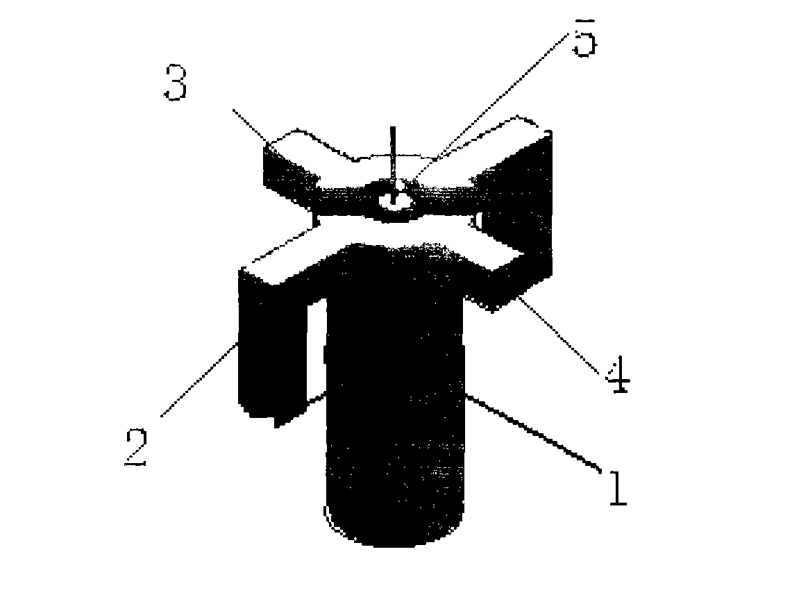
[0028] refer to figure 1 , in the embodiment described below, first use the existing computer technology combined with the three-dimensional electromagnetic field simulation software Ansoft HFSS to conduct electromagnetic simulation to complete the parameter design of the entire antenna. The cross pendant vibrator antenna unit is composed of the vibrator long pendant arm 2, the vibrator short arm 4 and the feed balun 5 located in the center of the coaxial metal tube 1 cylinder, which are radially symmetrically fixed around the upper end of the coaxial metal tube 1. , and the port of the coaxial metal tube 1 is formed with a choke groove 3 along the direction of the generatrix of the cylinder, and the two pairs of vibrator long arms 2 and vibrator short arms 4 are respectively symmetrical to both sides of the choke groove 3. Balun is the abbreviation of the English phrase "balanced and unbalanced". It is also called a balanced feeder or a balancer. A two-conductor device used...


PUM


Abstract

The invention provides a circularly polarized antenna array having a spinning characteristic in a space structure. The circularly polarized antenna array is provided with an antenna array face divided into a plurality of sub arrays. The antenna array face adopts a circularly polarized antenna sub array structure having the spinning characteristic and is divided into the plurality of rectangular sub arrays (10). Each of rectangular sub arrays (10) is provided with four spinning units which is equivalent to one spinning sub array in the space structure and adopts four pendulous cross dipole antenna units as a group, rectangular array arrangement is formed in a space, and four pendulous cross dipole antennas of each sub array are respectively arranged on top points of four corners of each rectangular array and are clockwise arranged in 0-degree, 90-dgree, 180-degree and 270-degree spinning mode. By adopting the circularly polarized antenna array, the circularly polarized radiation performance can be achieved well, and design size of each unit is not required to be changed.

Description

technical field [0001] The invention relates to a circularly polarized antenna sub-array structure with spin characteristics in space structure, and the circularly polarized array antenna adopting the sub-array has excellent circularly polarized radiation performance. Background technique [0002] Since Heinrich Hertz discovered the first radio link in 1886 in the Hertz Laboratory in Karsnow, Germany, the antenna as the entrance and exit of radio waves in human wireless communication has gone through a history of more than 120 years. From the simple electric spark signal at the beginning, to the later global positioning satellite and the phased array radar system for detection and positioning. For the requirements of antennas, human beings are no longer satisfied with just being able to transmit simple signals, but are researching and exploring more accurately, faster, and more conveniently. With the development of technologies such as satellite communication, telemetry and...

Claims


Application Information

Patent Timeline
IPC IPC(8): H01Q21/24H01Q1/36
Inventor 郑一农王建冯梅赵玉国陈斌
Owner LINGBAYI ELECTRONICS GRP
Why Eureka
Try Eureka