Rough-fine-movement laminated workbench with laser interferometer measurement

A technology of laser interferometer and workbench, which is applied in the direction of measuring devices, instruments, optical devices, etc., can solve the problem of not being able to meet the high speed, large load and high dynamic characteristics of lithography equipment, and not being able to adapt to the dual-station switching system, Problems such as poor structural integrity, to achieve the effect of compact structure, reducing the number of parts, and reducing the requirements for high precision

Active Publication Date: 2013-07-31
TSINGHUA UNIV +1
View PDF4 Cites 11 Cited by
  • Summary
  • Abstract
  • Description
  • Claims
  • Application Information

AI Technical Summary

Problems solved by technology

[0005] Due to factors such as the frictional damping nonlinearity of the support system, the first two types of micro-motion stages cannot meet the requirements of high speed, large load, and high dynamic characteristics of lithography equipment.
The micro-motion table with voice coil motor / air support can meet the requirements of lithography equipment, but it has the disadvantages of poor structural integrity, thick table body and high center of mass, and its performance is limited to a certain extent.
[0006] Tsinghua University applied for a six-degree-of-freedom precision stage on June 29, 2007 (application number: 200710118130.5), providing a six-degree-of-freedom precision stage for silicon wafer stages in lithography machines, using frictionless damping The voice coil motor is used as the driving structure, although the positioning accuracy is greatly improved, but the structure is bulky and not compact, and cannot well meet the needs of the dual switching system

Method used


Image

  • Rough-fine-movement laminated workbench with laser interferometer measurement
  • Rough-fine-movement laminated workbench with laser interferometer measurement
  • Rough-fine-movement laminated workbench with laser interferometer measurement

Examples


Embodiment Construction

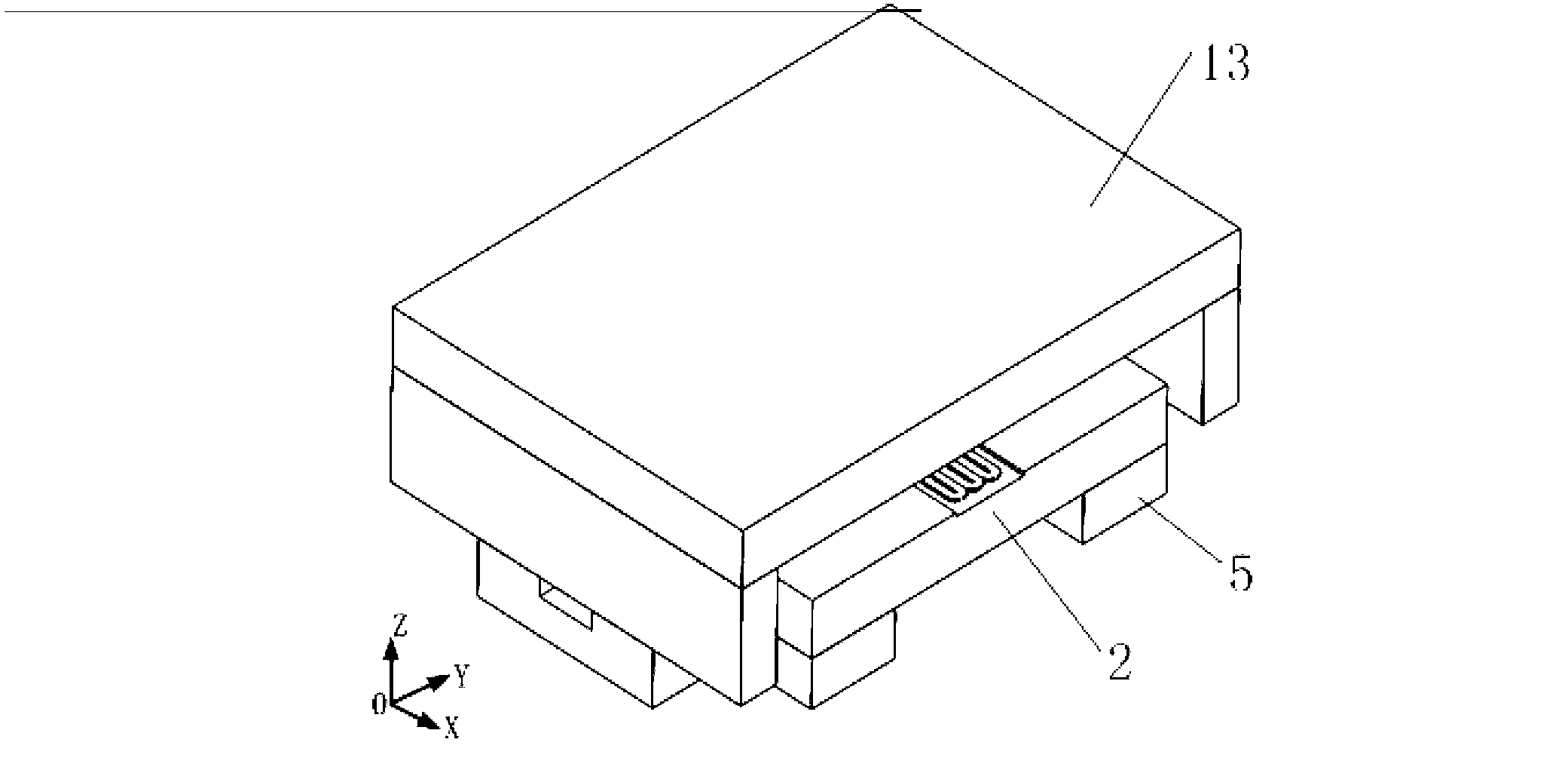
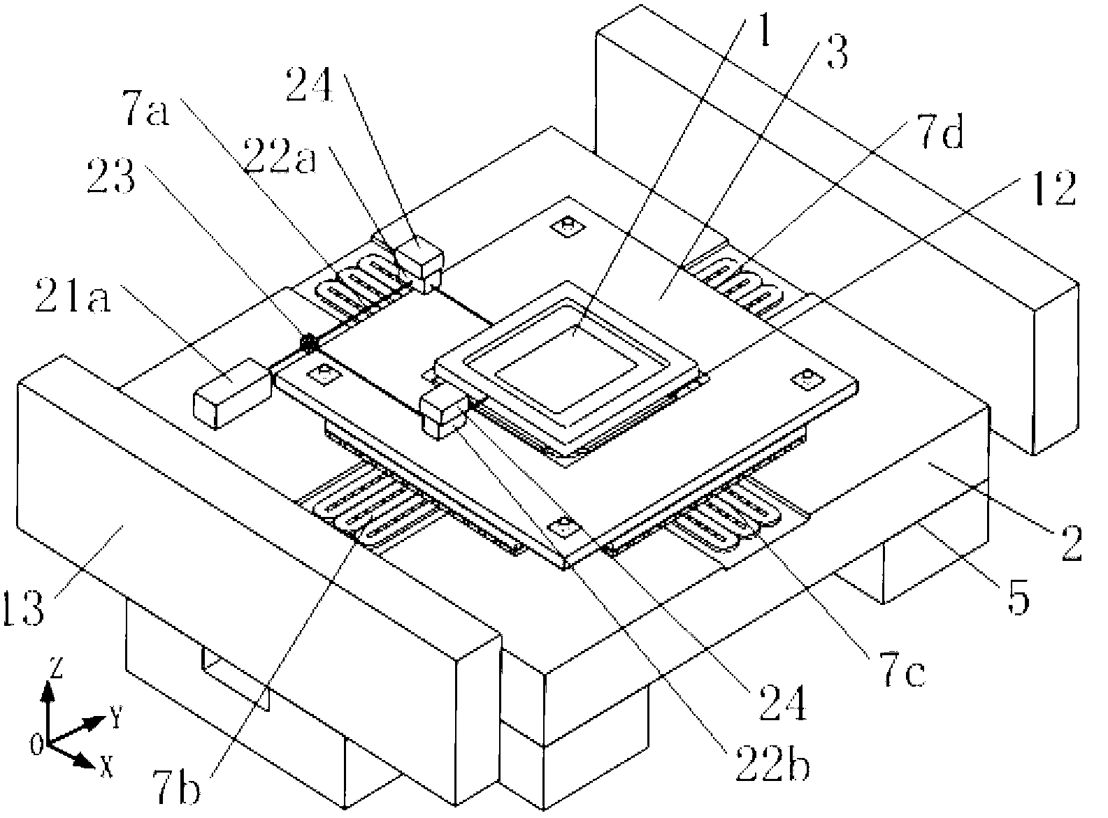
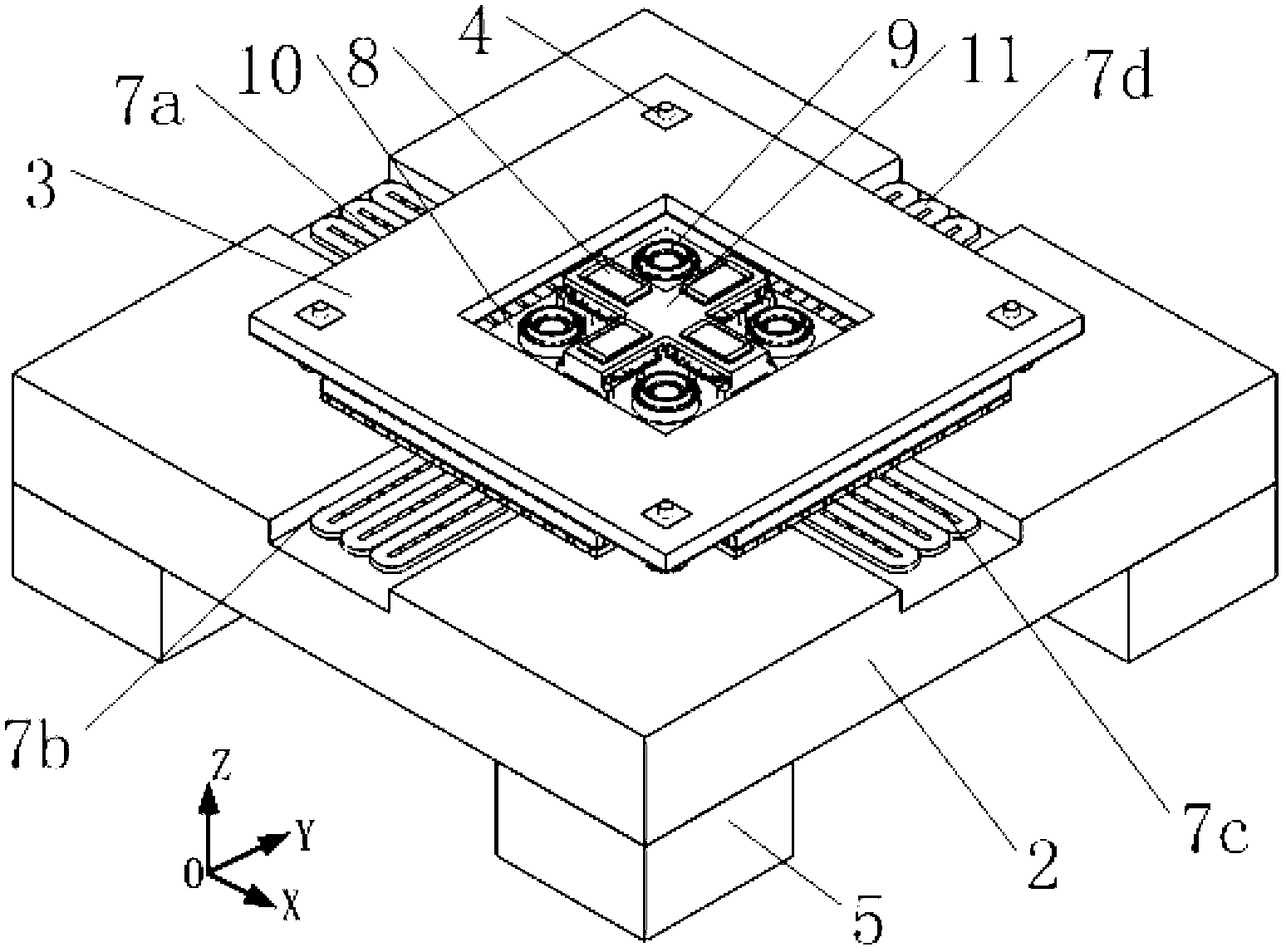
[0024] figure 1It is a three-dimensional structure diagram of a coarse-fine motion lamination workbench with laser interferometer measurement provided by the present invention. The workbench contains a fine motion table, a coarse motion table, a balance weight 2, a vibration isolator 5 and a measuring frame 13. The fine motion table and the coarse motion table are stacked on the upper surface of the balance weight, and the fine motion table is composed of a supporting piece table 1, a fine motion table mover frame 12, a fine motion table stator frame 10 and an electromagnetic drive module. The bearing table 1 is fixed on the top of the fine motion table mover skeleton 12, and the electromagnetic force drive module of the fine motion table includes four sets of the first three degrees of freedom movement in the horizontal plane along the X direction, the Y direction and around the Z axis. An electromagnetic force drive module 8 and four sets of second electromagnetic force dri...


PUM


Abstract

The invention relates to a rough-fine-movement laminated workbench with laser interferometer measurement. The workbench is mainly used in a lithography system. The laminated workbench comprises a fine movement bench, a rough movement bench, a balancing block, four vibration isolators, and a measuring frame. The rough movement bench comprises a rough movement bench frame, four moving iron electromagnetic driving modules, and four air bearings. The fine movement bench is arranged at the middle of the rough movement bench frame. The system also comprises a laser interferometer measurement assembly used in position feedback between a sheet bearing stage of a six degrees of freedom (DOF) positioning device and a pedestal. The laser interferometer measurement assembly is composed of a laser source, an optical path assembly, and a laser interferometer. With the laser interferometer measurement assembly, real-time six-DOF measurement can be carried out upon the movement part of the device. The workbench provided by the invention has a simple and compact structure. The mass of the movement parts is light. A rough movement bench driving motor adopts a lengthened rectangular coil group. On a basis that movement precision is not influenced, manufacturing difficulty of a large-scale halbach magnetic steel array is avoided, and driving motor stroke is increased, such that movement precision is improved.

Description

technical field [0001] The invention relates to a precision motion table, in particular to a six-degree-of-freedom precision motion table, which is mainly used in semiconductor photolithography equipment and belongs to the technical field of ultra-precision processing and detection equipment. Background technique [0002] The precision table with high precision and fast response has an extremely important position in modern manufacturing technology, and is regarded as an important symbol of a country's high-tech development level. In ultra-precision machine tools, the ultra-precision precision table is used to compensate the error of the feed system to achieve ultra-precision machining; in the manufacture of large-scale integrated circuits, the ultra-precision fine table is used Feed; In scanning probe microscope, the ultra-precision fine motion table is used to measure the surface topography of the sample and perform nano-processing; in bioengineering, the ultra-precision f...

Claims


Application Information

Patent Timeline
Patent Type & Authority Applications(China)
IPC IPC(8): G03F7/20G01B9/02
Inventor 朱煜张鸣杨开明成荣刘召刘昊徐登峰张利田丽叶伟楠张金胡金春穆海华尹文生赵彦坡秦慧超胡清平
Owner TSINGHUA UNIV
Why Eureka
Try Eureka