Forward-looking radar scanning coherent imaging method

A coherent imaging and forward-looking technology, which is applied in the field of radar imaging and high-speed platform radar forward-looking imaging, can solve problems such as complex synchronization, motion compensation, limitations, and limited azimuth resolution, so as to overcome the constraints of scene types and avoid The effect of synchronization

Active Publication Date: 2013-08-07
UNIV OF ELECTRONIC SCI & TECH OF CHINA
View PDF5 Cites 6 Cited by
  • Summary
  • Abstract
  • Description
  • Claims
  • Application Information

AI Technical Summary

Problems solved by technology

[0004] For moving platform radar forward-looking imaging, especially how to improve the azimuth resolution, the document "Airborne Radar Single Pulse Forward-looking Imaging Algorithm" ("China Image Graphics" 2010, 15 (3): P462-469 ) uses monopulse technology for beam sharpening, which is based on the principle of monopulse angle measurement and is suitable for strong point targets. For complex landforms, due to the existence of multiple scattering centers, serious angular scintillation will occur; the literature "A new Sector Imaging Radar for Enhanced Vision–SIREV” (SPIE Conference on Enhanced and Synthetic Vision, 1999, pp.39-47, Florida), using array antennas to form apertures to achieve forward-looking imaging, but the size of the platform limits the antenna aperture The expansion of the azimuth resolution is limited; the document "Bistatic Forward-looking Synthetic Aperture Radar" (Inter

Method used


Image

  • Forward-looking radar scanning coherent imaging method
  • Forward-looking radar scanning coherent imaging method
  • Forward-looking radar scanning coherent imaging method

Examples


Embodiment Construction

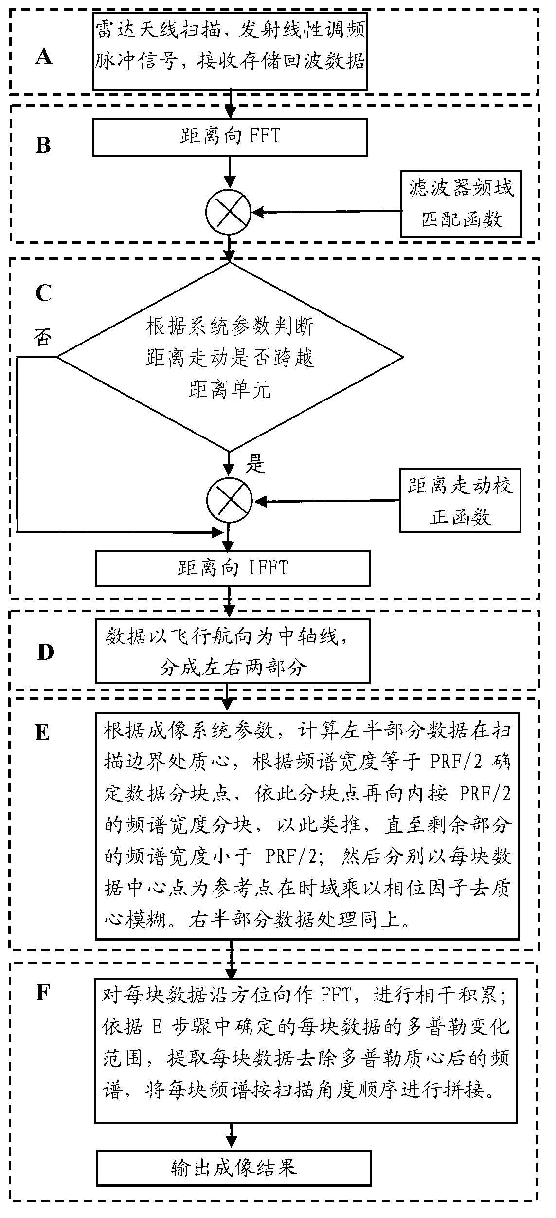
[0025] Embodiments of the present invention will be further described below in conjunction with the accompanying drawings.

[0026] The specific measuring method of this embodiment is:

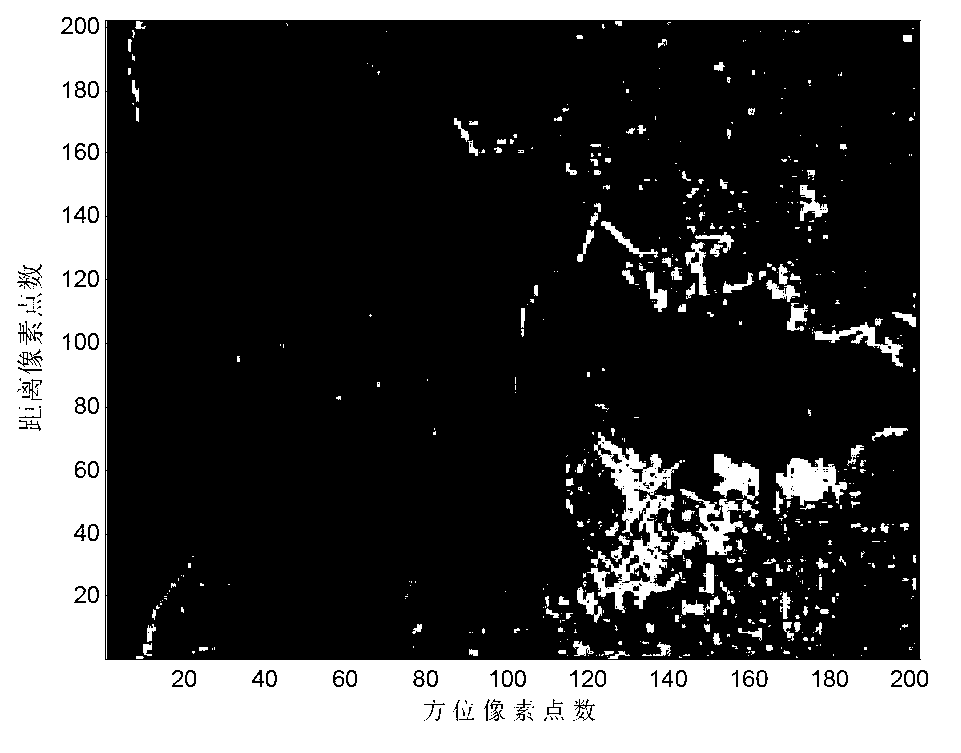
[0027] A. The schematic diagram of radar forward-looking scanning in this implementation is as follows figure 2 As shown, where the radar antenna azimuth beamwidth is θw =3°, the antenna scans the ±10° area directly in front of the aircraft, and the scanning area scene is as follows image 3 As shown, the scanning speed is ω=30° / s, the moving speed of the carrier aircraft is v=600m / s, PRF=1500Hz, the wavelength of the signal transmitted by the transmitter is λ=0.0086m, the bandwidth is B=2MHz, and the frequency modulation slope is K r =3.33×10 10 Hz / s linear frequency modulation pulse signal, after coherent demodulation of the forward-looking scanning radar point target echo signal, it is expressed as:

[0028] s ( t , τ ...


PUM


Abstract

The invention discloses a forward-looking radar scanning coherent imaging method. The forward-looking radar scanning coherent imaging method particularly includes enabling a high-speed platform to carry a scanning radar antenna, scanning space on the forward side of a desired track, transmitting millimeter-wave or submillimeter-wave linear frequency modulation signals and acquiring echo; and dividing the echo into a left portion and a right portion by using the right forward-looking direction as a boundary, respectively processing sub-blocks of data of the left portion and the right portion, removing Doppler centroid blurs of the sub-blocks of the data and performing coherent integration and connection for the sub-blocks of the data to finally implement high-resolution imaging for a forward-looking region. The forward-looking radar scanning coherent imaging method has the advantages that high-resolution imaging for the forward-looking region can be quickly and effectively implemented, constraints of scene types and limitation of the size of the platform are overcome, and problems of complexity in implementing synchronization, movement compensation and the like are solved.

Description

technical field [0001] The invention belongs to the technical field of synthetic aperture radar and relates to radar imaging, in particular to a high-speed platform radar forward-looking imaging method. Background technique [0002] Synthetic Aperture Radar (SAR) uses the Doppler frequency change caused by the azimuth movement of the radar platform relative to the ground target to obtain high-resolution images in azimuth. Compared with optical sensors, it has the unique advantages of penetrability, all-day and all-weather working ability. At present, side-looking and squint SAR have been widely used in the fields of earth remote sensing, resource exploration, reconnaissance, surveying and mapping, and disaster forecasting. [0003] However, when the antenna beam points to the forward-looking, the echo Doppler frequency of the left and right symmetrical ground targets on both sides of the heading will be blurred. Due to the small size, the conventional single-base SAR cannot...

Claims


Application Information

Patent Timeline
IPC IPC(8): G01S13/90
Inventor 李文超杨建宇黄钰林夏永红蒋文
Owner UNIV OF ELECTRONIC SCI & TECH OF CHINA
Why Eureka
Try Eureka