Standby power supply charge-discharge control circuit for far-end communication base station
A charging and discharging control and backup power technology, which is applied in the field of communication, can solve problems such as low stability and reliability, and complex charging and discharging control circuits for remote communication base station backup power.
- Summary
- Abstract
- Description
- Claims
- Application Information
AI Technical Summary
Problems solved by technology
Method used
Image

Examples
Embodiment 1
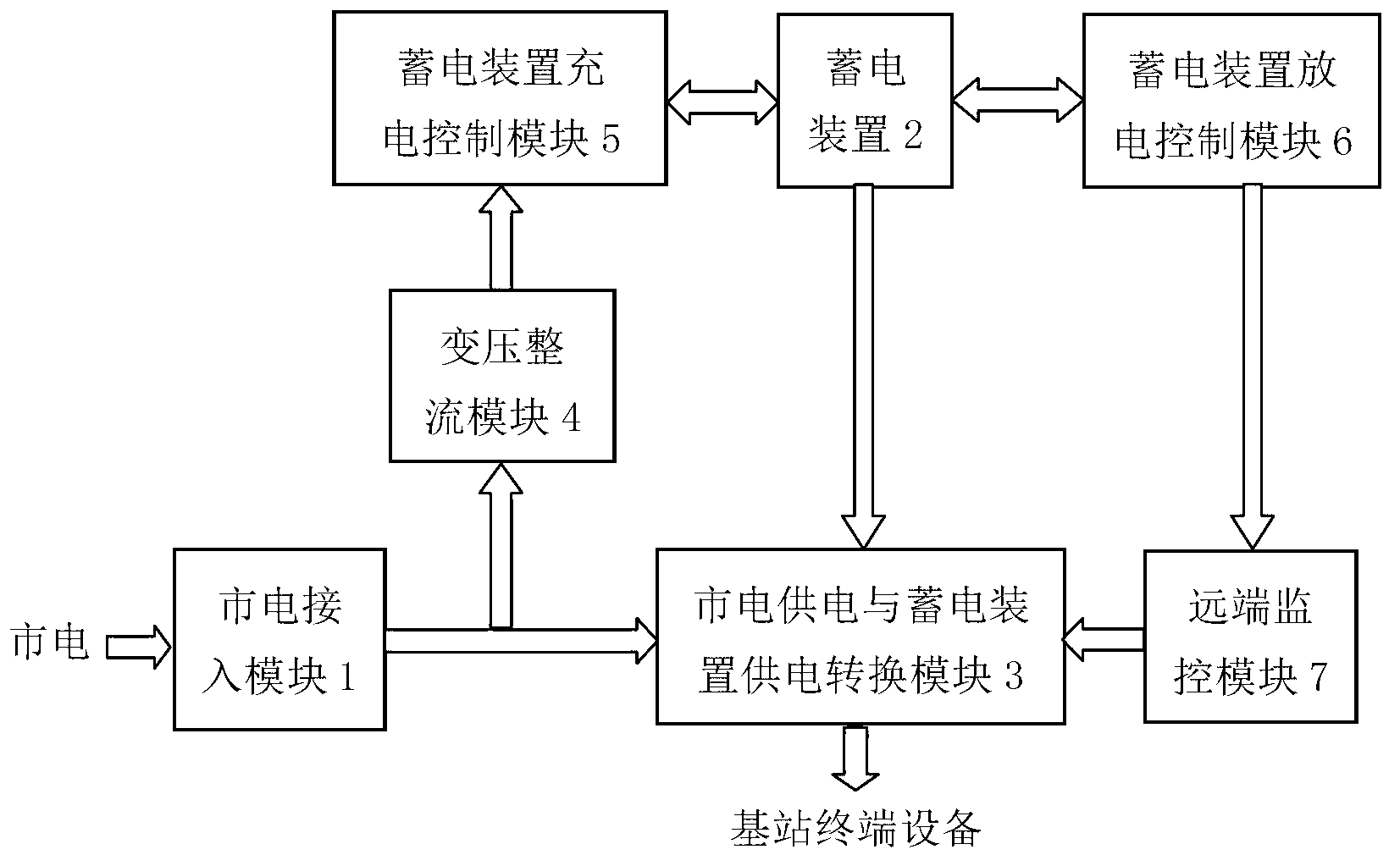
[0055] This embodiment provides a remote communication base station backup power supply charge and discharge control circuit, its structural block diagram is as follows figure 1 As shown, in this embodiment, the remote communication base station backup power supply charge and discharge control circuit includes a mains power access module 1, a power storage device 2, a mains power supply and power storage device power conversion module 3, and a transformer rectification module 4 , the charging control module 5 of the electric storage device and the discharging control module 6 of the electric storage device.
[0056] The mains power access module 1 is used for mains power connection and includes an output terminal for externally outputting alternating current.
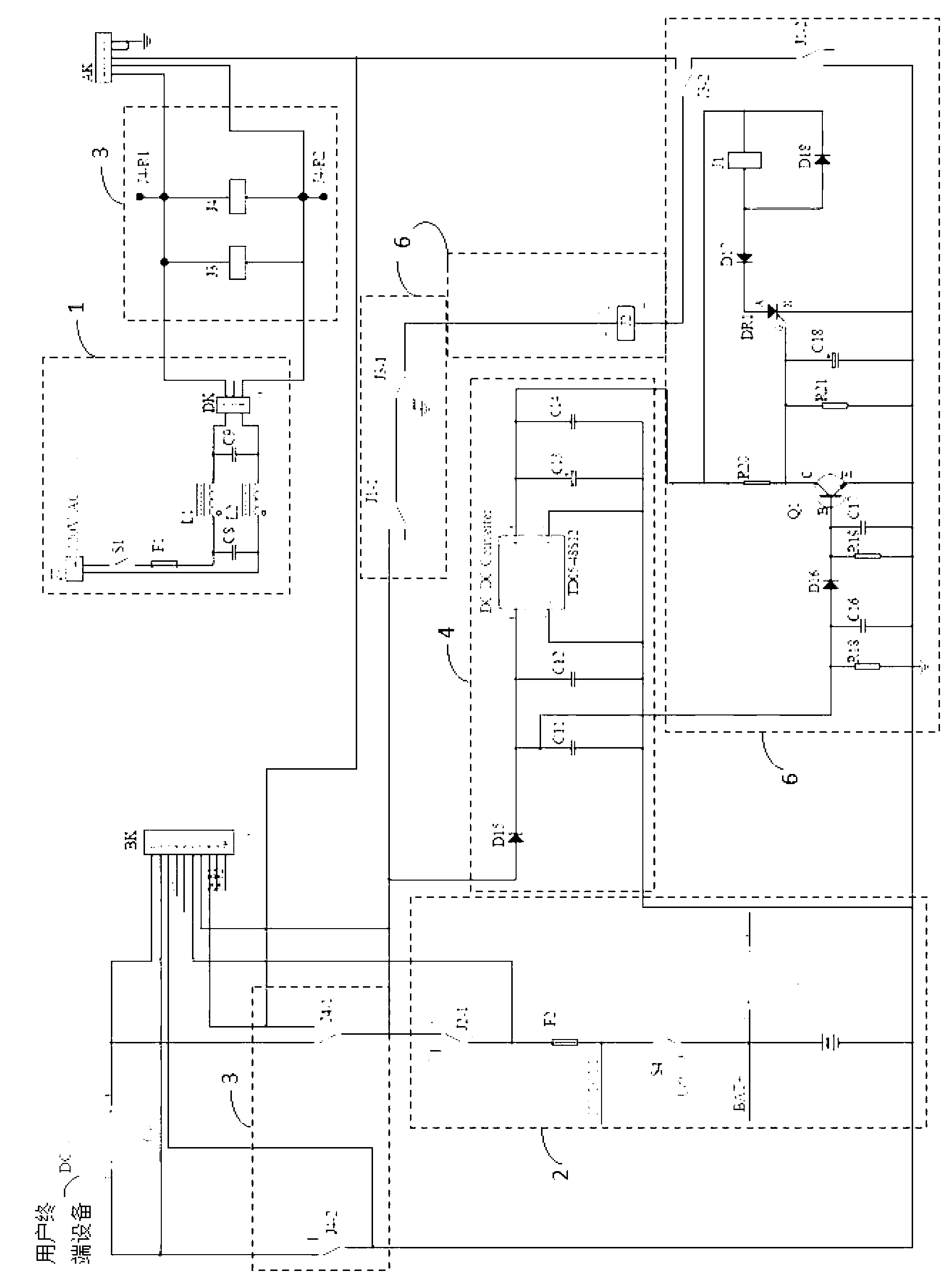
[0057] Such as figure 2As shown, the mains access module 1 includes a switch S1, an insurance component F1, common mode inductors L1, L2, capacitors C8, C9; one end of the switch S1 is connected to the positive pole o...
Embodiment 2
[0091] In this embodiment, on the basis of the above embodiments, the discharge control module 6 of the electric storage device further includes a debugging unit 8 for debugging the magnitude of the current passing through the undervoltage detection control unit. Such as Figure 5 As shown, the debugging unit 8 includes resistors R16, R17, and a capacitor C15. One end of the resistor R16 is used as the input terminal of the debugging unit 8 and connected to the output terminal of the DC / DC transformer unit. The resistor R16 The other end of the resistor R17 is connected to one end of the resistor R17, one end of the capacitor C15, and the other end of the capacitor C15 is grounded; the other end of the resistor R17 is used as the output terminal of the debugging unit 8 to connect to the undervoltage detection input to the control unit. By replacing the resistor R16 to limit the size of the base current passing through the triode Q2, the preset lower limit voltage of the stora...
Embodiment 3
[0094] In this embodiment, on the basis of the above-mentioned embodiments, the remote communication base station backup power supply charge and discharge control circuit also includes a remote monitoring module 7 for remote monitoring of its working status, and the remote monitoring module 7 is a dynamic Ring monitoring system interface FK; the mains power supply and power storage device power supply conversion module 3 also includes a first signal sending unit for sending the mains power supply and power storage device 2 working status signals to the remote monitoring module 7, so The first signal sending unit is the changeover contacts 3 and 4 of the relay J1, and the electric storage device discharge control module 6 also includes a second signal sending unit for sending to the remote monitoring module 7 whether the electric storage device 2 is undervoltage. unit, the second signal sending unit is the changeover contact 4 of the relay J3.
[0095] Such as Figure 6 As sho...
PUM
 Abstract
Description
Claims
Application Information
 - R&D
- Intellectual Property
- Life Sciences
- Materials
- Tech Scout
- Unparalleled Data Quality
- Higher Quality Content
- 60% Fewer Hallucinations
Browse by: Latest US Patents, China's latest patents, Technical Efficacy Thesaurus, Application Domain, Technology Topic, Popular Technical Reports.
© 2025 PatSnap. All rights reserved.Legal|Privacy policy|Modern Slavery Act Transparency Statement|Sitemap|About US| Contact US: help@patsnap.com