
Electric hydraulic excavator sharing direct-current bus

A hydraulic excavator, DC bus technology, applied in the direction of mechanically driven excavators/dredgers, etc., can solve the problems of throttling loss, no change, etc., and achieve the effect of simplified structure, simple structure, and convenient recycling and reuse

Active Publication Date: 2013-08-21
TAIYUAN UNIV OF TECH
View PDF19 Cites 16 Cited by
  • Summary
  • Abstract
  • Description
  • Claims
  • Application Information

AI Technical Summary

Problems solved by technology

Many domestic companies have applied for similar utility model patents and invention patents, such as the utility model patent "electric excavator", patent number ZL 200620120546.1; "electric hydraulic excavator", patent number ZL 200720139425.6; "electric excavator for shaft construction" , patent No. ZL 200820004895.6; "Electric Hydraulic Excavator", patent No. 200820113727.0; a new type of electrohydraulic excavator, application number 201120263102. . 4; "A power system for an electric excavator", application number 201110074783.4; however, these patented technologies only replace the internal combustion engine with an electric motor, and the main structure and control method of the excavator remain basically unchanged, and the traditional valve control method, and failed to make full use of the principle of electric control to recycle the kinetic potential energy wasted in the work of the excavator, so there is a very large throttling loss, which needs further improvement

Method used


Image

  • Electric hydraulic excavator sharing direct-current bus
  • Electric hydraulic excavator sharing direct-current bus
  • Electric hydraulic excavator sharing direct-current bus

Examples


specific Embodiment approach 1

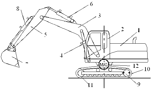
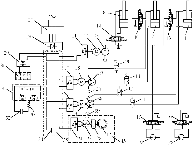
[0061] The boom hydraulic cylinder 4 and the control loop that drive the boom up and down are the loops of compound control of the pump and the valve.

[0062] The arm hydraulic cylinder 6 and the control circuit for driving the arm are a compound control circuit of a pump and a valve.

[0063] The bucket hydraulic cylinder 8 and the control circuit for driving the bucket are open loops controlled by valves.

[0064] The swing control circuit 45 is a system directly controlled by the electric motor.

[0065] A further feature is that the boom hydraulic cylinder and the control circuit are composed of the boom hydraulic cylinder 4, the boom inverter 36, the boom motor 37, the boom hydraulic pump 38, the open circuit inverter 21, the Type circuit motor 22, open circuit hydraulic pump 23, boom control valve 13, first two-position two-way valve 41, second two-position two-way valve 42; the output end of the boom inverter 36 is connected to the boom The motor 37 controls the...

specific Embodiment approach 2

[0074]

[0075] In this embodiment, an electrohydraulic excavator sharing a DC bus, as attached figure 1 and 4 As shown, its composition relationship is as follows:

specific Embodiment approach 3

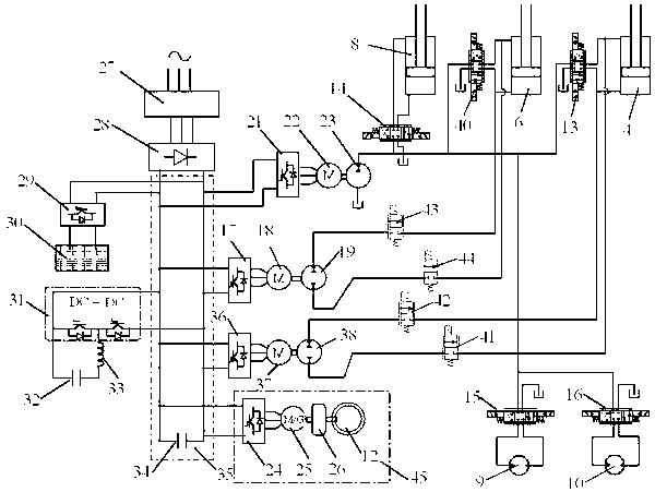
[0076] The boom hydraulic cylinder 4 and the control loop that drive the boom up and down are the loops of compound control of the pump and the valve.

[0077] The stick hydraulic cylinder 6 and the control circuit for driving the stick are the combined control loop of the pump and the valve.

[0078] The bucket hydraulic cylinder 8 and the control circuit for driving the bucket are valve-controlled open loops.

[0079] The swing control circuit 45 is a system directly controlled by the electric motor.

[0080] Above-mentioned boom hydraulic cylinder and control circuit are composed of boom hydraulic cylinder 4, boom inverter 36, boom motor 37, boom hydraulic pump 38, open circuit inverter 21, open circuit motor 22, open circuit The loop hydraulic pump 23, the boom control valve 13, the first two-position two-way valve 41, and the second two-position two-way valve 42; wherein, the output end of the boom inverter 36 is connected to the boom motor 37 to control The speed a...


PUM


Abstract

An electric hydraulic excavator sharing a direct-current bus is provided with the common direct-current bus which is electrically connected with an input end of a bucket rod inverter, an input end of an open loop inverter, an input end of a rotating inverter and an input end of a movable arm inverter. A control loop of a movable arm hydraulic cylinder is a closed loop directly controlled by a pump or an open loop controlled by a valve or a loop controlled by the pump and the valve in a composite mode. A control loop of a bucket rod hydraulic cylinder is a closed loop directly controlled by a pump or an open loop controlled by a valve or a loop controlled by the pump and the valve in a composite mode. A control loop of a bucket hydraulic cylinder is an open loop controlled by a valve. A rotating control loop is a system directly controlled by a motor. Electrodynamic force is used in the excavator, structure is simple, efficiency is high, maintaining is convenient, construction cost is greatly lowered, no tail gas is exhausted during construction, and environment protection is achieved.

Description

technical field [0001] The invention relates to a hydraulic excavator driven by a motor, in particular to a hydraulic excavator which adopts grid electric energy and battery electric power to drive a plurality of electric motors sharing a DC bus as a power source. Background technique [0002] A hydraulic excavator, which is one of construction machines, generally has an undercarriage, an upper revolving body rotatably installed on the undercarriage, and an upper revolving body that can be pitched on the upper revolving body and includes a boom, an arm, and a bucket. A multi-joint work device. At present, the power source of the hydraulic excavator mainly adopts the internal combustion engine, which drives the hydraulic pump, and controls the multiple hydraulic actuators through the control valve, specifically the hydraulic cylinder for the boom, the hydraulic cylinder for the stick, and the hydraulic cylinder for the bucket. Hydraulic cylinders and rotary hydraulic motor...

Claims


Application Information

Patent Timeline
Patent Type & Authority Applications(China)
IPC IPC(8): E02F3/43E02F3/36
Inventor 权龙程珩权仲翊李斌
Owner TAIYUAN UNIV OF TECH
Learn More