Post-unfreezing water burst prevention method of non-full-depth freezing vertical shaft

A non-full-depth, freezing method, which is applied in wellbore lining, shaft equipment, earthwork drilling and production, etc., can solve problems such as poor timing of grouting, failure to achieve grouting effect, and poor grouting effect. It achieves the effects of significant water prevention and control, convenient construction and operation, and strong impermeability

Inactive Publication Date: 2013-09-04
XIAN UNIV OF SCI & TECH +1
View PDF3 Cites 29 Cited by
  • Summary
  • Abstract
  • Description
  • Claims
  • Application Information

AI Technical Summary

Problems solved by technology

[0003] At present, there are several defects in the prevention and control technology of water gushing after thawing by the wellbore freezing method: 1. The timing of grouting is not good to choose, the grouting is too early, the cracks in the surrounding rock have not yet formed, the treatment effect is not good, the grouting is too late, and the water gushing is very large , the grout is completely washed out by water, and the grouting effect cannot be achieved
2. The form of grouting. A single grouting method is not very injectable for water-rich and weakly permeable formations
Third, the determination of the grouting position, once the position is not determined properly, it will cause too much grouting workload, and the grouting effect is not good

Method used


Image

  • Post-unfreezing water burst prevention method of non-full-depth freezing vertical shaft
  • Post-unfreezing water burst prevention method of non-full-depth freezing vertical shaft
  • Post-unfreezing water burst prevention method of non-full-depth freezing vertical shaft

Examples


Embodiment 1

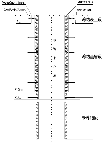
[0042] refer to figure 1 , figure 2 , image 3 , Figure 4 , Figure 5 Shown, a kind of non-full deep-frozen vertical well thaws the water inrush prevention method after thawing, and this method is carried out according to the following steps:

[0043] 1) Determination of grouting form

[0044] After the wellbore is thawed, the fissures in the surrounding rocks are connected, and the water gushing out from the fissures in the surrounding rocks is relatively large. In areas with rich water and weak seepage, the general grouting form is difficult to inject or the injection effect is not good. Combined use of high and low pressure, deep and shallow holes combined grouting method;

[0045] 2) Determination of the timing of wellbore water prevention and control:

[0046] (1) In order to ensure the safe construction of the lower shaft and the horse head gate in the construction of the unfrozen section, during the construction of the lower shaft and the horse head door, the up...

Embodiment 2

[0072] Main well grouting scheme

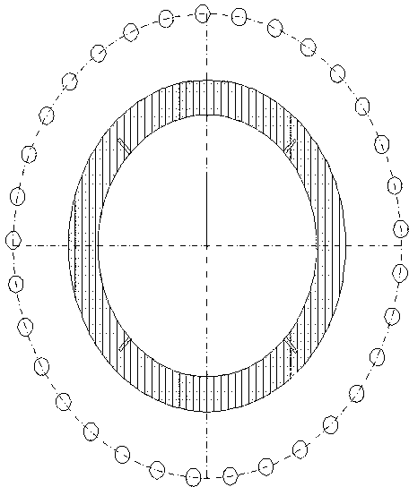
[0073] (1) Fabrication and layout of grouting pipes

[0074] The grouting hole uses YT-28 wind hammer, together with 42mm "one"-shaped drill bit drills holes, the hole depth passes through the well wall and enters the surrounding rock 1000mm, six holes are arranged on each level and grouting pipes are installed, and the upper and lower horizontal holes should be staggered. Note Slurry pipe adopts Made of 32㎜ seamless steel pipe, one end is equipped with a horse tooth buckle, and the other end is equipped with an inner threaded buckle piping cap. The length is processed according to the wall thickness. The grouting pipe is wound with hemp silk and driven into the hole. The exposed length shall not exceed 50mm.

[0075] (2) Configuration of slurry

[0076] The grouting uses two types of single liquid cement slurry and cement water glass double liquid slurry. Its application principle is based on single-liquid slurry, supplemented by doubl...

Embodiment 3

[0094] Auxiliary Well Grouting Scheme

[0095] (1) drilling

[0096] The grouting hole construction uses the YTP-26 air leg rock drill mm drill bit and hollow hexagonal steel drill to drill holes, and special pipe burying device to bury pipes.

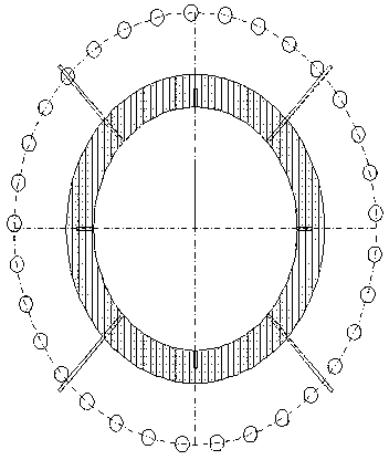
[0097] The position of the grouting hole behind the wall of the bedrock section is determined according to the actual position of the water outlet point. Generally, the holes are arranged within 1m of the water outlet point. Before construction, experienced veteran workers carry out on-site positioning. The hole depth is preferably 0.5m through the wall of the bedrock section and into the rock. The specification of the grouting pipe is φ38×600mm.

[0098] The interwall grouting is carried out in layers. Starting from the vertical depth -234m, the horizontal filling grouting holes with a distance between layers of 50m are evenly arranged in the four directions of the well wall, and the pipe is buried in the way of casing. First use...


PUM


Abstract

The invention discloses a post-unfreezing water burst prevention method of a non-full-depth freezing vertical shaft. The method comprises grouting form determination, water prevention opportunity determination, grouting position determination, grouting hole arrangement, grouting material preparation, grouting pressure setting, and grouting pipe manufacturing and installation, wherein single-liquid grouting serves as the main grouting, and double-liquid grouting serves as auxiliary grouting; the single-liquid grouting comprises, by mass ratio, water and portland cement with a ratio of 0.6:1 to 1.25:1; the double-liquid grouting comprises, by mass ratio, portland cement, sodium silicate and triethanolamine with a ratio of 1:1: (0.1%-0.25%); the high-pressure and the low-pressure are used simultaneously, during grouting, the working pressure is 1.2 to 1.5 times the hydrostatic pressure of the grouting position, and the final grouting pressure is 2-2.5 times the hydrostatic pressure of the grouting position; and deep holes and shallow holes are combined, a freezing surface soil section utilizes wall clearance grouting, a freezing bedrock section utilizes the wall clearance grouting and backwall grouting, a shallow hole grouting pipe is Phi 38 mm*600 mm, and a deep hole grouting pipe is Phi 38 mm*3100 mm. The post-unfreezing water burst prevention method of the non-full-depth freezing vertical shaft is convenient to construct and operate, strong in groutability and watertightness, good in compaction, high in strength and applicable to post-unfreezing vertical shafts.

Description

technical field [0001] The invention relates to a method for preventing and controlling water gushing in a vertical shaft, in particular to a method for preventing and controlling water gushing in a non-fully deep-frozen vertical shaft after thawing. Background technique [0002] my country has built more than 700 frozen shafts since the first successful application of the freezing method in the Kailuan Linxi wind shaft in 1955. However, after the shafts are thawed, new cracks will appear in the surrounding rock, and the seepage channels of the rocks will change. The law of water gushing will also change. When the amount of water gushing is so large that it is impossible to meet the construction requirements only by drainage, grouting to block the water source channel and then drainage becomes the main control measure. Grouting water plugging is to press cement slurry or chemical slurry into the underground rock formation gap, crack or roadway through the pipeline to make it ...

Claims


Application Information

Patent Timeline
Patent Type & Authority Applications(China)
IPC IPC(8): E21D11/38E21D11/10
Inventor 任建喜王蓬马忙利谢冬季张琨陈海安郑赞赞占有名王松陈江孙杰龙孟昌
Owner XIAN UNIV OF SCI & TECH
Why Eureka
Try Eureka