
Small feet-lock guide pipe with steel plate connection

A technology of small conduits and locking feet, used in mining equipment, earthwork drilling, installation of bolts, etc., can solve the problems of loss of support, difficult to guarantee quality, small contact area, etc., to improve construction progress, reduce construction time, improve The effect of engineering quality

Active Publication Date: 2013-09-04
云南交投集团云岭建设有限公司
View PDF4 Cites 6 Cited by
  • Summary
  • Abstract
  • Description
  • Claims
  • Application Information

AI Technical Summary

Problems solved by technology

[0003] However, there are also problems in the construction of the lock-foot anchor. First, the lock-foot anchor is basically at a horizontal angle. When the mortar anchor is used for construction, it is difficult to fill the horizontal hole with grout, and the construction is very inconvenient, so most of them use anchoring agent. , and although the anchoring agent and anchor bolt are simple in the plant method and less in the auxiliary facilities, the quality is difficult to guarantee
The second is that the connection between the lock foot anchor rod and the I-beam in the initial support is not firm. Due to the small contact area, spot welding is often used for connection, and the quality is difficult to guarantee. A slight external force will cause the solder joints at the connection to fall off and lose support and lock feet. the role of

Method used


Image

  • Small feet-lock guide pipe with steel plate connection
  • Small feet-lock guide pipe with steel plate connection
  • Small feet-lock guide pipe with steel plate connection

Examples


Embodiment Construction

[0020] Attached below Figure 1-4 The present invention is further described.

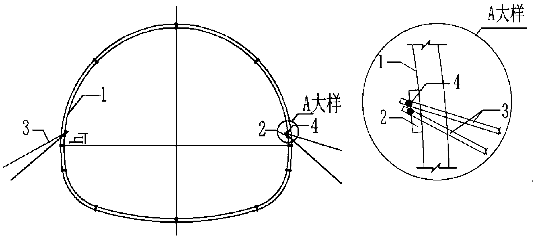
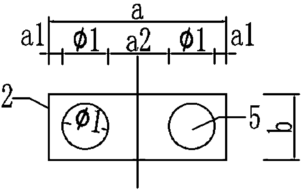
[0021] exist Figure 1-3 Among them, a small foot-locking conduit connected by a steel plate is composed of two small foot-locking conduits 3 , a foot-locking steel plate 2 and two stop rings 4 . It is characterized in that a foot-locking steel plate 2 with two symmetrical round holes 5 is welded to the I-beam 1 that needs to be locked; a small foot-locking conduit 3 with a grouting hole 6 drilled on the body passes through the foot-locking steel plate The round hole 5 of 2 is driven in the surrounding rock; Cover a steel bar limit ring 4 on the exposed head of the pin-locking conduit 3, as the pin-locking steel plate 2 and the pin-locking conduit 3 welded and fixed connectors.

[0022] exist figure 1 , the I-beam 1 is the I-beam in the initial support of the tunnel.

[0023] exist figure 2 Among them, the lock foot steel plate 2 is a rectangular steel plate with sufficient rigidity, the leng...


PUM


Abstract

The invention relates to a small feet-lock guide pipe with steel plate connection. The small feet-lock guide pipe is characterized in that a feet-lock steel plate with two symmetric round holes is welded on H-shaped steel to be locked at feet, small feet-lock guide pipes drilled with mortar injection holes penetrate the round holes of the feet-lock steel plate to be hit into wall rock, a reinforcing steel bar limit ring is sleeved at one end of each small feet-lock guide pipe and used as a connector for welding and fixing the feet-lock steel plate and the small feet-lock guide pipes. By the small feet-lock guide pipe, the wall rock and the small feet-lock guide pipes can be tightly connected, the small feet-lock guide pipes are fixedly connected with the H-shaped steel in preliminary bracing, so that the purposes of controlling restraint, controlling arch and controlling integral submergence of the ground are achieved. Members can be processed and manufactured industrially, the steel plate and the H-shaped steel can be welded in advance outside a tunnel, construction time in the tunnels is shortened, construction progress and construction quality are improved, and construction environment inside the tunnel is improved. The small feet-lock guide pipe is safe, reliable and convenient to operate, and meets requirements of safety, quality, progress, economic benefits, social benefits and the like.

Description

technical field [0001] The invention relates to a component for primary support of a tunnel, in particular to a small conduit with locking feet connected by a steel plate. Background technique [0002] During the construction of tunnels with weak surrounding rocks, it is particularly important to prevent and treat excessive deformation and even collapse of tunnels. For this reason, tunnel builders have summed up some engineering measures to prevent and treat excessive deformation of soft surrounding rock tunnels in long-term theoretical research and engineering practice, and have achieved some remarkable achievements, such as grouting to strengthen weak surrounding rock mass, Improve initial support stiffness, add long bolts and locking foot bolts, etc. Lock foot anchor is a new technology developed in recent years. Because of its simplicity, economy and obvious effect, it greatly improves the construction efficiency, saves other auxiliary construction measures, and saves m...

Claims


Application Information

Patent Timeline
IPC IPC(8): E21D21/00
Inventor 张星江
Owner 云南交投集团云岭建设有限公司
Learn More