High-accuracy high-spatial resolution long range profile detection system

A long-range surface shape detection, high spatial resolution technology, applied in measurement devices, instruments, optical devices, etc., can solve the problem of increasing the system structure and computational complexity, unable to fully reflect the focusing performance of the optical components to be measured, and the air-floating transmission table. Large rotation error and other problems, to achieve the effect of improving measurement accuracy

Active Publication Date: 2013-09-04
INST OF HIGH ENERGY PHYSICS CHINESE ACAD OF SCI
View PDF5 Cites 21 Cited by
  • Summary
  • Abstract
  • Description
  • Claims
  • Application Information

AI Technical Summary

Problems solved by technology

However, there are generally the following problems: (1) Due to the flaws of the optical components in LTP, which greatly limit the performance of LTP, the best LTP accuracy in the world (only 0.2 microrad) still cannot reach nanometer Focusing requirements cannot fully reflect the focusing performance of the optical components to be tested (references: Rommeveaux, A., L. Assoufid, et al. (2007). Second metrology round-robin of APS, ESRF and SPring-8 laboratories of elliptical and spherical hard-x-ray mirrors, San Diego, CA, USA, SPIE.p.2278-2280(1995); Qian, S. and K. Qian(2010).Study and considerations of nanometer and nano-radian surface profiler , SPIE, P.O.BOX 10 Bellingham WA 98227-0010 USA.); (2) and the highest measurable surface shape error spatial frequency is 1 line per millimeter (line per millimeter), which can reflect very little information on surface shape errors; (3) During the scanning process of the optical head, the rotation error of the air-bearing transmission table is very large, the order of magnitude is several microradians. Although the reference mirror can be used to compensate for this error, this increases the complexity of the system structure and calculation

Method used


Image

  • High-accuracy high-spatial resolution long range profile detection system
  • High-accuracy high-spatial resolution long range profile detection system
  • High-accuracy high-spatial resolution long range profile detection system

Examples


Embodiment 1

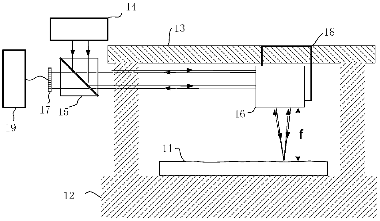
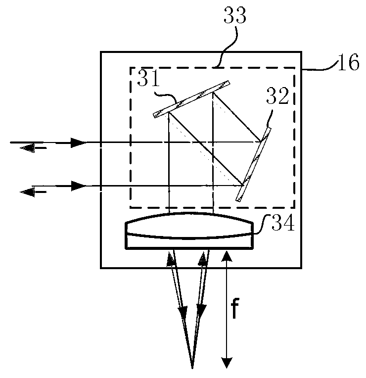
[0026] refer to figure 1 , the high-spatial resolution and high-precision long-range surface shape detection system includes: object to be measured 11, granite basic worktable 12, high-precision air-floating transmission table 13, laser light source assembly 14, beam splitting prism 15, scanning optical head 16, detector Array 17 , optical element support 18 , signal acquisition and processing module 19 .

[0027] The object 11 to be measured is located in the detection area of ​​the granite basic workbench 12, the high-precision air-floating transmission platform 13 is supported by the granite basic workbench 12, and the optical element support 18 is fixed on the motion guide rail of the high-precision air-flotation transmission platform 13. The scanning optical head 16 is fixed on the optical element support 18 .

[0028]The stable and collimated light emitted by the laser light source assembly 14 is horizontally deflected by the beam splitting prism 15, and moves in the s...


PUM


Abstract

The invention discloses a high-accuracy high-spatial resolution long range profile detection system, which comprises a workbench, a transmission platform, a laser light source, a scanning optical head, a beam splitting prism and a signal acquisition processing unit, wherein the scanning optical head is arranged on the transmission platform; the beam splitting prism is used for deflecting light output from the laser light source for incidence into the scanning optical head, and an incident direction is consistent with the scanning direction of the transmission platform; the scanning optical head is used for deflecting and focusing incident light beams to the surface of an object to be detected in a detection area, for the object to be detected, of the workbench; and light reflected by the surface of the object to be detected in the detection area for the object to be detected sequentially passes through the scanning optical head and the beam splitting prism, and enters the signal acquisition processing unit. The system can be used for the high-spatial frequency sampling measurement of the surface to be detected, and the measurement accuracy is high; and the system can be used for measuring a large-sized object, and is particularly suitable for the detection of an optical element on a synchrotron radiation beam.

Description

technical field [0001] The invention relates to the surface shape detection of large-scale mirror objects, in particular to a high-space resolution and high-precision long-distance surface shape detection system. Background technique [0002] The surface error of the optical element surface has a very important impact on the performance of the optical system. According to the distribution of the spatial frequency of the surface error, it can be divided into high spatial frequency, medium spatial frequency and low spatial frequency error. The existing research results show that different frequency errors have different effects on the imaging system. For example, the refraction effect of high-frequency errors and the scattering effect of low-frequency errors will not significantly change the shape of the point spread function on the image plane, but will only cause the focus energy to change. Divergence, reduction of imaged contrast and signal-to-noise ratio, in contrast, the ...

Claims


Application Information

Patent Timeline
Patent Type & Authority Applications(China)
IPC IPC(8): G01B11/24
Inventor 杨福桂李明盛伟繁刘鹏
Owner INST OF HIGH ENERGY PHYSICS CHINESE ACAD OF SCI
Why Eureka
Try Eureka