
Method for co-production of trifluoroethylene and hydrogen fluoride

A technology of trifluoroethylene and hydrogen fluoride, which is applied in the fields of fluorine/hydrogen fluoride, chemical instruments and methods, and preparation of dehydrohalogenation, etc., and can solve problems such as potential safety hazards, insufficient utilization of anhydrous hydrogen fluoride, and no economic benefits

Inactive Publication Date: 2013-09-11
TONGJI UNIV
View PDF10 Cites 14 Cited by
  • Summary
  • Abstract
  • Description
  • Claims
  • Application Information

AI Technical Summary

Problems solved by technology

The above-mentioned method all has the problem that the conversion efficiency of HFC-134a is not high, the life-span of catalyst is short, and BF 3 Dangerous items that are flammable, explosive, highly toxic and react violently with water, which will bring safety hazards during use
In addition, the large amount of anhydrous hydrogen fluoride produced in this process has not been fully utilized and has not produced economic benefits

Method used


Image

  • Method for co-production of trifluoroethylene and hydrogen fluoride
  • Method for co-production of trifluoroethylene and hydrogen fluoride

Examples


Embodiment 1

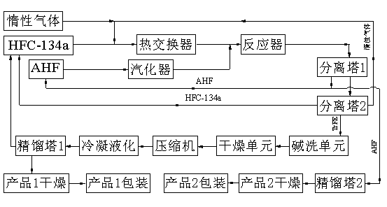
[0033] refer to figure 1 : A certain amount of α-Al 2 o 3 into the reactor bed. According to HFC-134a and CO 2 The molar ratio is 1:5, HFC-134a and CO are fed 2 The gas forms a mixed gas, and enters the reactor after passing through the heat exchanger. -1 The reaction is carried out at the space velocity; the reacted gas is recycled through the HF gas separated by the first separation tower, and the HF gas can also be separated through the second rectification tower, and then dried to obtain HF gas with a purity of more than 99.9%. The separated tail gas is further separated through the separation tower, TrFE, HFC-134a, CO 2 Gas and other trace components enter the second separation tower for further separation, HFC-134a and CO 2Gas recycling, the separated TrFE and other trace components are washed and dried with alkali, then compressed by a compressor, condensed and liquefied, and then enter a rectification tower for rectification. The trace non-condensable gas can be ...

Embodiment 2

[0036] refer to figure 1 : A certain amount of α-Al 2 o 3 Put it into the reactor bed, vaporize AHF in the vaporization chamber, and fluoride at 260°C and 400°C for 2 and 4 hours, respectively. According to HFC-134a and N 2 The molar ratio is 1:5, HFC-134a and CO are fed 2 The gas forms a mixed gas, and enters the reactor after passing through the heat exchanger. -1 The reaction is carried out at the space velocity; the reacted gas is recycled through the HF gas separated by the first separation tower, and the HF gas can also be separated through the second rectification tower, and then dried to obtain HF gas with a purity of more than 99.9%. The separated tail gas is further separated through the separation tower, TrFE, HFC-134a, CO 2 Gas and other trace components enter the second separation tower for further separation, HFC-134a and CO 2 Gas recycling, the separated TrFE and other trace components are washed and dried with alkali, then compressed by a compressor, cond...

Embodiment 3

[0039] refer to figure 1 : A certain amount of γ-Al 2 o 3 into the reactor bed. According to HFC-134a and CO 2 The molar ratio is 1:9, HFC-134a and CO are fed 2 The gas forms a mixed gas, and then enters the reactor after passing through the heat exchanger. -1 The reaction is carried out at the space velocity; the reacted gas is recycled through the HF gas separated by the first separation tower, and the HF gas can also be separated through the second rectification tower, and then dried to obtain HF gas with a purity of more than 99.9%. The separated tail gas is further separated through the separation tower, TrFE, HFC-134a, CO 2 Gas and other trace components enter the second separation tower for further separation, HFC-134a and CO 2 Gas recycling, the separated TrFE and other trace components are washed and dried with alkali, then compressed by a compressor, condensed and liquefied, and then enter a rectification tower for rectification. The trace non-condensable gas c...


PUM


Abstract

The invention relates to a method for the co-production of trifluoroethylene and hydrogen fluoride, and is used for producing the trifluoroethylene in a hydrogen fluoride removing manner by taking 1,1,1,3-tetrafluoroethane as a main raw material as well as co-producing the hydrogen fluoride. The method comprises the following steps: mixing HFC-134a (1,1,1,2-tetrafluoroethane) and an inert gas at a molar ratio f 1:(1-20); performing a reaction of removing HF (Hydrogen Fluoride) from the HFC-134a in a fixed bed reactor through an acid catalyst under the conditions that the temperature ranges from 300 to 650 DEG C, the air speed ranges from 300 to 2000h<-1> and the pressure ranges from 0.1 to 0.8Mp; separating tail gas in a first separation tower; pretreating the catalyst and producing an anhydrous hydrogen fluoride product through the cyclic utilization of the separated hydrogen fluoride; realizing the cyclic utilization of the HFC-134a and the inert gas after separating the HFC-134a with a low boiling point, the inert gas and the trifluoroethylene in a second separation tower; performing alkaline cleaning, drying, compression and condensation liquefaction on the trifluoroethylene; then enabling the trifluoroethylene to enter a first rectifying tower; finally drying and packaging the trifluoroethylene treated in the first rectifying tower. The method is suitable for the production of the trifluoroethylene, and belongs to an atomic economic reaction. The two reaction products have important economic values; the conversion rate of the HFC-134a is high; the selectivity and yield of the trifluoroethylene as a main product are high.

Description

technical field [0001] The invention relates to a chemical preparation method, in particular to a method for producing trifluoroethylene and co-producing hydrogen fluoride. Background technique [0002] Trifluoroethylene (TrFE), as an important fluorine-containing olefin, is currently mainly used in the synthesis of fluoropolymers. This type of fluoropolymer not only has thermal stability, chemical resistance stability and UV resistance stability, but also has the solubility and melt processability of conventional polymers, and also has ferroelectricity, piezoelectricity, Unique electrical properties such as pyroelectricity and high dielectricity have wide application value in electronics, military, medical and other industries. [0003] The main synthesis methods of trifluoroethylene monomer reported in current literature and patents are: [0004] (1) CFC-113 hydrodechlorination method: 2CF 2 ClCFCl+H 2 → 2CF 2 =CHF + 6HCl [0005] (2) CFC-1123 hydrodechlorination me...

Claims


Application Information

Patent Timeline
Patent Type & Authority Applications(China)
IPC IPC(8): C07C21/18C07C17/25C01B7/19B01J21/04
CPCY02P20/584
Inventor 朱志荣贾文志魏建华
Owner TONGJI UNIV
Learn More