X-ray detector and manufacturing method thereof

A detector and X-ray technology, applied in the field of semiconductor devices and their manufacturing, can solve problems such as alignment accuracy error tolerance, interconnection bonding quality, etc.

Active Publication Date: 2013-09-11
INST OF MICROELECTRONICS CHINESE ACAD OF SCI
View PDF3 Cites 15 Cited by
  • Summary
  • Abstract
  • Description
  • Claims
  • Application Information

AI Technical Summary

Problems solved by technology

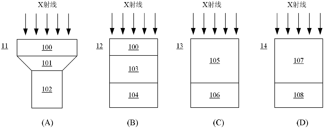
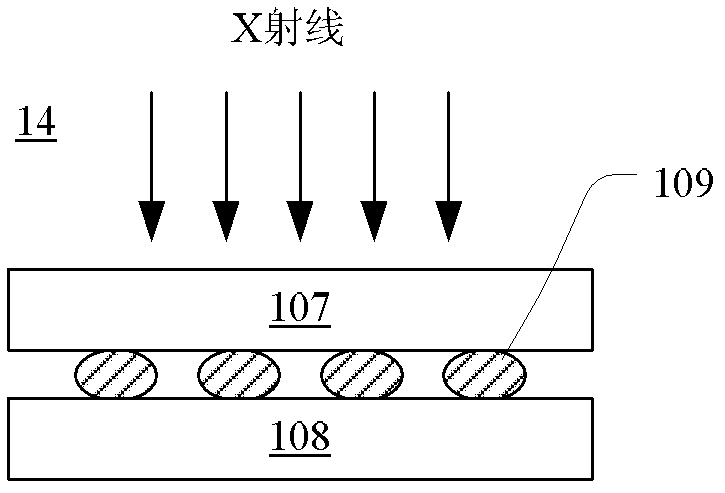
[0011] However, the size of the pixel unit of the X-ray detector is between tens and hundreds of microns, the size of the bonding bump is smaller than the size of the general packaging electrode (hundreds of microns to millimeters), a

Method used


Image

  • X-ray detector and manufacturing method thereof
  • X-ray detector and manufacturing method thereof
  • X-ray detector and manufacturing method thereof

Examples


Embodiment Construction

[0021] Hereinafter, the present invention will be described in more detail with reference to the accompanying drawings. In the various drawings, for the sake of clarity, various parts in the drawings are not drawn to scale.

[0022] In the following, many specific details of the present invention are described, such as device structures, materials, dimensions, processing techniques and techniques, for a clearer understanding of the present invention. However, the invention may be practiced without these specific details, as will be understood by those skilled in the art. Unless otherwise specified below, various parts in the semiconductor device may be composed of materials known to those skilled in the art.

[0023] In the present application, the term "semiconductor structure" refers to a semiconductor substrate formed after undergoing various steps of manufacturing a semiconductor device and all layers or regions that have been formed on the semiconductor substrate.

[00...


PUM


Abstract

The invention discloses an X-ray detector and a manufacturing method thereof. The X-ray detector comprises an interconnection substrate, bonding interconnection, a photovoltaic conversion device chip and a CMOS pixel reading chip, wherein the bonding interconnection penetrates through the interconnection substrate and is exposed out of the two main surfaces of the interconnection substrate, the photovoltaic conversion device chip is bonded with one main surface of the interconnection substrate, the CMOS pixel reading chip is bonded with the other main surface of the interconnection substrate, and a bonding pad of the photovoltaic conversion device chip is electrically connected with a bonding pad of the CMOS pixel reading chip through the bonding interconnection. According to the X-ray detector, working processes can be simplified, and reliability and yield can be improved.

Description

technical field [0001] The present invention relates to semiconductor devices and methods of manufacturing the same, and more particularly, to X-ray detectors and methods of manufacturing the same. Background technique [0002] X-ray is an ultrashort electromagnetic wave with a wavelength of about 10-0.01 nanometers, corresponding to a frequency of 3×10 16 Hz to 3×10 19 Between Hz, the energy corresponding to the wave-particle duality is between 120eV and 120keV. X-rays are neutral high-energy photon streams, which have super penetrating effects on the irradiated objects, as well as fluorescence, heating, photosensitive, ionization and other effects. After the X-ray passes through the object, its intensity or phase changes due to the absorption and scattering of the object. The content of the signal change is related to the material, structure, thickness, defect and other characteristics of the object, so it can be applied to non-contact objects through signal detection I...

Claims


Application Information

Patent Timeline
IPC IPC(8): H01L27/146G01T1/20
Inventor 殷华湘王玉光董立军陈大鹏
Owner INST OF MICROELECTRONICS CHINESE ACAD OF SCI
Why Eureka
Try Eureka