
Annular lighting device for eye ground camera

A ring lighting and camera technology, applied in the fields of medical optics and fundus microscopic imaging, can solve the problems of high cost of the ring diaphragm, low energy utilization rate of the lighting system, uneven retinal illumination, etc., so as to improve the utilization rate of light energy and shorten the Response time, effect of good lighting effects

Inactive Publication Date: 2013-09-18
CHANGCHUN INST OF OPTICS FINE MECHANICS & PHYSICS CHINESE ACAD OF SCI
View PDF11 Cites 12 Cited by
  • Summary
  • Abstract
  • Description
  • Claims
  • Application Information

AI Technical Summary

Problems solved by technology

[0005] The invention provides a ring lighting device for the fundus camera to solve the problems of low energy utilization rate of the lighting system, uneven lighting of the retina and high cost of using the ring diaphragm in the existing fundus camera

Method used


Image

  • Annular lighting device for eye ground camera
  • Annular lighting device for eye ground camera
  • Annular lighting device for eye ground camera

Examples


specific Embodiment approach 1

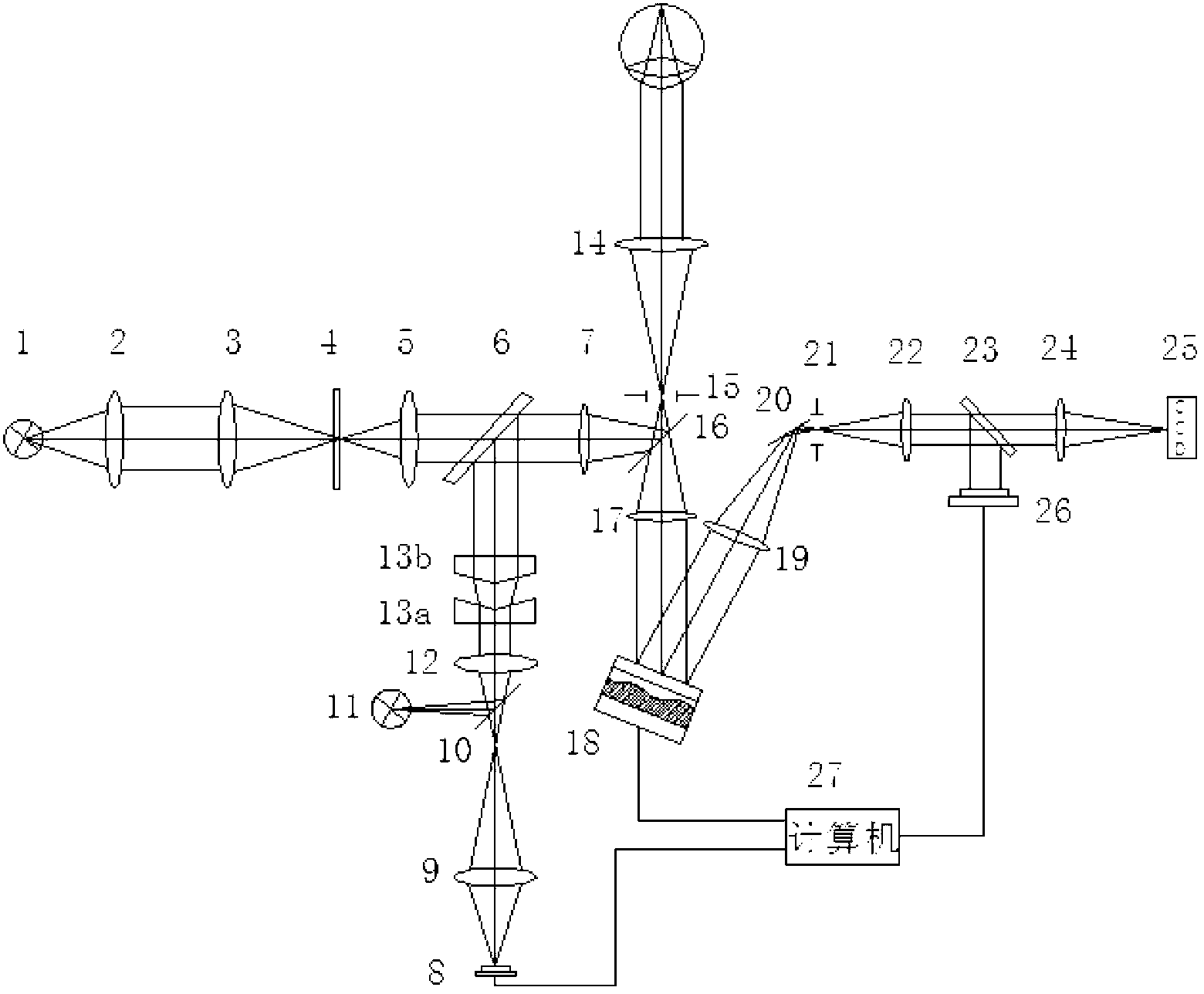
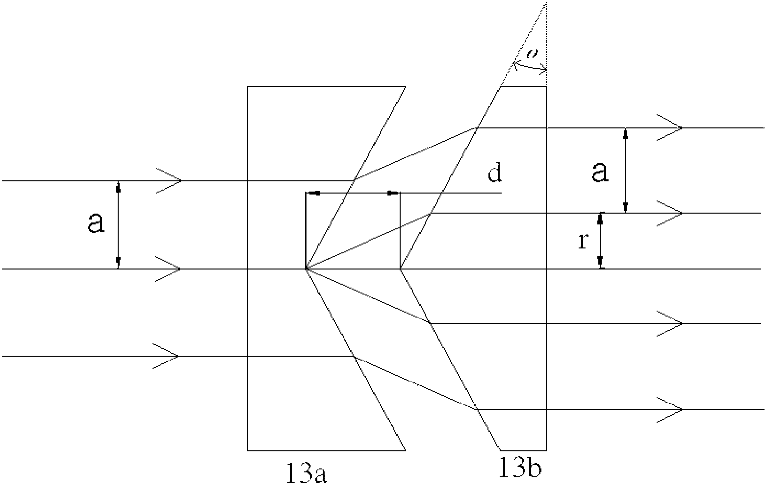
[0012] Specific implementation mode 1. Combination figure 1 and figure 2 Describe this embodiment, a ring-shaped lighting device for a fundus camera; it is set in a fundus camera mainly composed of an illumination optical system, a diopter adjustment optical system, and an adaptive optics imaging system. An axicon lens is added to the illumination optical system to realize the circular light beam irradiating the edge of the cornea of ​​the human eye, avoiding the central area of ​​the cornea with strong reflection.

[0013] A ring-shaped lighting device for a fundus camera, which is installed in a fundus camera mainly composed of an illumination optical system, a diopter adjustment optical system, and an adaptive optical imaging system. The axicon lens group 13 then forms an annular parallel light beam, and the inner diameter of the annular light spot can be adjusted by adjusting the distance between the negative axicon lens 13a and the positive axicon lens 13b. The inner d...

specific Embodiment approach 2

[0018] Specific embodiment 2. This embodiment is an example of the application of the annular lighting device described in specific embodiment 1 in a fundus camera: the fundus camera also includes a diopter adjustment system and an adaptive optics imaging system;

[0019] The laser light source 1 in the diopter adjustment optical system emits light, illuminates the reticle 4 of the visual mark after the first lens 2 and the second 3, and makes the reticle 4 pass through the conjugate lens group (the third lens 5 and the relay mirror 7 ) is imaged at the filter aperture 15 . The human eye observes the image of the reticle 4 at the filter aperture 15 through the eye lens 14 . Simultaneously, the eyepiece objective lens 14 can be moved back and forth until the image of the reticle 4 is clearly seen by the human eye. At this time, it can be considered that the primary aberration has been preliminarily automatically corrected by the human eye. Turn on the detection light source 11...


PUM


Abstract

An annular lighting device for an eye ground camera relates to the field of medical optics, and solves the problems that the utilization rate of lighting system energy is low, retina lighting is not uniform, and annular diaphragm with high cost is used in the conventional eye ground camera. A lighting source sent out by a light source generates uniform annular faculae after passing through a lighting optical system; the uniform annular faculae light cornea edge areas of people, and can keep away from cornea central areas capable of strongly reflecting light, so that the uniformity of eye ground lighting is improved; further, the width of annular light beams can be changed through adjusting the distance between a positive axial conical mirror and a negative axial conical mirror in a lighting light path to be adapted to different eyes of people; and real images are formed in the middle of the system for two times, the influence of stray light such as cornea reflected light on the imaging quality is greatly reduced through adding confocal filtering apertures and adopting a reflecting mirror foldable light path.

Description

technical field [0001] The invention relates to the field of medical optics, in particular to the field of fundus microscopic imaging. technical background [0002] By observing the retinal capillaries of the human eye, the patient's retinopathy and changes in the systemic microcirculation system can be correctly diagnosed. However, the human eye is a complex optical system, and even normal human eyes inevitably have certain aberrations. The thickness and refractive index of each refractive medium inside the human eye are not uniform, and the surface curvature of different human eyes deviates seriously. After light enters the eyeball in nature, although it can illuminate the fundus of the human eye, the light is too weak to be used for imaging the fundus of the human eye. Since the reflected light of the human cornea is too strong compared to the brightness of the fundus, the fundus camera must include an illumination system that can illuminate the fundus of the human eye ...

Claims


Application Information

Patent Timeline
Patent Type & Authority Applications(China)
IPC IPC(8): A61B3/14A61B3/12
Inventor 巩岩李春才
Owner CHANGCHUN INST OF OPTICS FINE MECHANICS & PHYSICS CHINESE ACAD OF SCI
Learn More