Carbonyl fluoride purifying method

A purification method and carbonyl fluoride technology, applied in the direction of carbonyl chloride, fractionation, etc., can solve the problems of high impurity gas content, low carbonyl fluoride purity, and difficulty in separating and purifying carbonyl fluoride.

Active Publication Date: 2013-09-18
PERIC SPECIAL GASES CO LTD
View PDF5 Cites 8 Cited by
  • Summary
  • Abstract
  • Description
  • Claims
  • Application Information

AI Technical Summary

Problems solved by technology

[0008] For COF in the prior art 2 The purity of carbonyl fluoride in the crude product gas is low, the content of impurity gas is high, and it is difficult to separate and purify to obtain the defects of carbonyl fluoride. The purpose of the present invention is to provide a method for purifying carbonyl fluoride. It has the advantages of high safety, high purity and more economical

Method used


Image

  • Carbonyl fluoride purifying method

Examples


Embodiment 1~10

[0030] Among the following examples 1-10:

[0031] The pressures are absolute pressures;

[0032] The purified gas test method is as follows:

[0033] The gas was introduced into gas chromatography-mass spectrometry (GC-MS) (model: Shimadzu Corporation GC-2014) and Fourier transform infrared spectrometer (FT-IR) (model: Nicolet6700) to analyze the gas composition. It is determined by GC-MS and FT-IR that the main component of the gas is carbonyl fluoride, and the purity and yield of carbonyl fluoride are calculated according to the integrated area of ​​carbonyl fluoride as a result of gas chromatography data.

[0034] The gas chromatographic determination uses He gas as the carrier gas and TCD detector, the He carrier gas flow rate is 100mL / min, the column temperature is 40°C, the inlet temperature is 100°C, and the TCD temperature is 100°C. The maximum peak on the gas chromatogram It is the chromatographic peak of carbonyl fluoride.

Embodiment 1

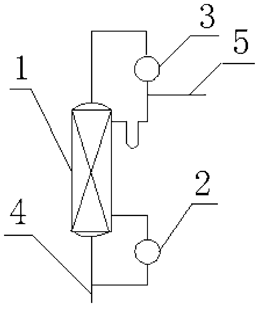
[0036] The purification device used in this example is as figure 1 The rectification tower shown includes a reboiler 2, a rectification column 1, a condenser 3, an inlet pipe 4 and a product take-off pipe 5. Wherein, the reboiler 2, the rectification column 1, and the condenser 3 are arranged sequentially from bottom to top, and the inlet pipe 4 is connected with the bottom of the reboiler 2 of the rectification tower and the bottom of the rectification column 1 respectively, and the reboiler of the rectification tower 2 The top is connected with the lower part of the rectification column 1, the top of the rectification column 1 is connected with the top of the condenser 3, the bottom of the condenser 3 is connected with the upper part of the rectification column 1, and the product extraction pipe 5 is located at the bottom of the condenser 3 and the rectification column 1 between the tops. The inlet pipe 4 is used for feed, and the product take-out pipe 5 is used for taking ...

Embodiment 2

[0048] The specific surface area of ​​the filler in the purification device used in this embodiment is 2500m 2 / m 3 , all the other are with embodiment 1.

[0049] COF 2 The crude product gas enters the rectification tower through the inlet pipe 4 of the rectification tower for purification, and the COF 2 The specific components of the crude product gas and the volume percentage of each component are shown in Table 2.

[0050] Step 1. Preliminary distillation and purification

[0051] During light removal treatment, the temperature of the reboiler 2 of the rectification tower is -48°C, the pressure is 0.6MPa, the temperature of the condenser 3 is 0.5°C lower than that of the reboiler 2, and the low-boiling point impurities accumulate in the condenser 3 at the top of the tower. By vacuuming, the low-boiling impurities accumulated in the condenser 3 at the top of the tower are removed; during weight removal, the temperature of the reboiler 2 of the rectification tower is 80°...


PUM

PropertyMeasurementUnit
sizeaaaaaaaaaa
sizeaaaaaaaaaa
heightaaaaaaaaaa

Abstract

The invention relates to a carbonyl fluoride purifying method and belongs to the technical field of fluorine chemical industry and electronic industry gases. The purifying method comprises the following steps of: firstly, performing light component removal and heavy component removal treatment on the crude product gas of COF2, wherein during the light component removal treatment, the temperature at the bottom of a purifying device ranges from -112 to 48 DEG C, the pressure at the bottom ranges from 0.01 to 0.6 MPa, and the temperature of the top is 0.5-30 DEG C lower than that of the bottom, during the heavy component removal treatment, the temperature at the bottom of the purifying device ranges from minus 81 to 80 DEG C, the pressure at the bottom ranges from 0.01 to 0.6 MPa, and the temperature of the top is 0.5-30 DEG C lower than that of the bottom; then obtaining an initial refined mixed gas; performing secondary refining purification, wherein the temperature at the bottom of the purifying device ranges from minus 123 to 36 DEG C, the pressure at the bottom ranges from 0.01 to 1.03 MPa, and the temperature of the top is 0.2-45 DEG C lower than that of the bottom; then obtaining the purified gas. The purifying method is especially suitable for the crude product gas of COF2 high in CO2 content; the COF2 purity in the purified gas is greater than or equal to 99%, and the CO2 content therein is less than 1000 ppm.

Description

technical field [0001] The invention relates to a method for purifying carbonyl fluoride, belonging to the technical fields of fluorine chemical industry and electronic industry gas. Background technique [0002] At present, in semiconductor manufacturing equipment and liquid crystal manufacturing processes, gases represented by perfluorocarbons, such as perfluorocarbons (PFC) or nitrogen trifluoride (NF 3 ), as a conventional etching gas and cleaning gas, but the above-mentioned conventional gases usually have a large global warming potential (GWP, Global Warming Potential) value, all of which are greenhouse gases. In order to reduce the greenhouse effect, it is necessary to develop substitute products. [0003] Carbonyl fluoride (COF 2 ), also known as carbon-based fluorine, fluorophosgene, has excellent cleaning properties, the cleaning effect is not inferior to perfluorocarbon and nitrogen trifluoride, and has a lower GWP value. Due to the coexistence of carbonyl fluo...

Claims


Application Information

Patent Timeline
Patent Type & Authority Applications(China)
IPC IPC(8): C01B31/00B01D3/14C01B32/80
CPCB01D3/14C01B32/80
Inventor 蒋玉贵冀延治徐海云沙婷郭绪涛纪振红
Owner PERIC SPECIAL GASES CO LTD
Why Eureka
Try Eureka