Hydraulic power generation system

A technology of generators and control systems, applied in the direction of engine components, machines/engines, mechanical equipment, etc., can solve problems such as not being vigorously developed

Inactive Publication Date: 2013-10-02
郑胜洪 +1
View PDF2 Cites 1 Cited by
  • Summary
  • Abstract
  • Description
  • Claims
  • Application Information

AI Technical Summary

Problems solved by technology

[0003] Most of the traditional hydropower generation is realized by damming rivers and dams, which inevitably suffer f

Method used


Image

  • Hydraulic power generation system
  • Hydraulic power generation system
  • Hydraulic power generation system

Examples


Embodiment 1

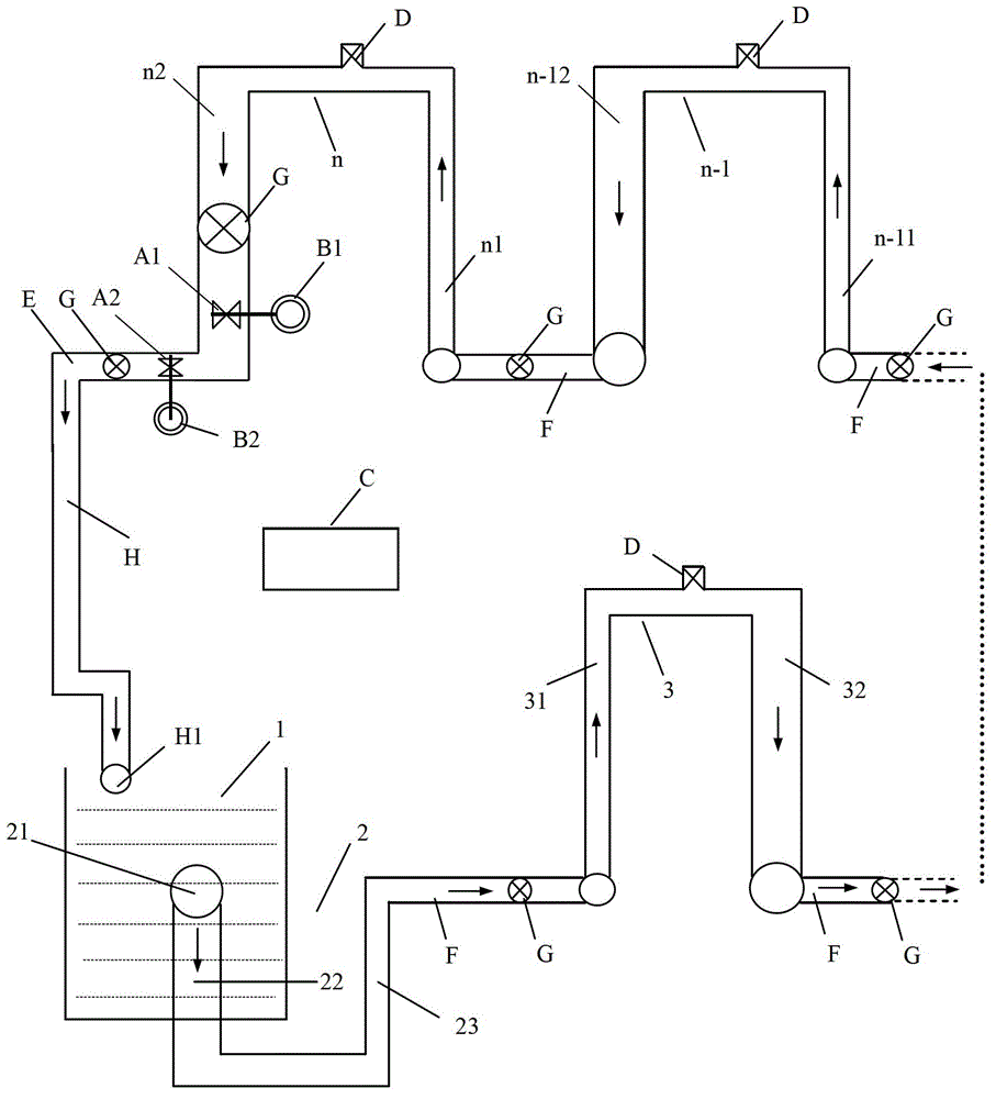
[0033] see figure 1 , the embodiment of the present invention is provided with water source 1, n-level U-shaped pipe, main water turbine A1, auxiliary water turbine A2, main generator B1, auxiliary generator B2, power transmission and control system C; The water outlet 21 is set in the water source 1 below the water surface of the water source by 2m, and the diameter of the first-stage water inlet pipe (thick pipe) 22 is larger than the diameter of the first-stage water outlet pipe (thin pipe) 23, so as to enhance the water pressure; The diameter of the second-stage water inlet pipe 31 of the second-stage U-shaped pipe 3 is smaller than the diameter of the second-stage water outlet pipe 32, which is used to convert the water pressure difference into a weight difference. By analogy, the n-level U-shaped tubes are connected in series in sequence. In addition to the U-shaped pipe 2 of the first stage, each U-shaped pipe is equipped with a water injection port D with safety press...

Embodiment 2

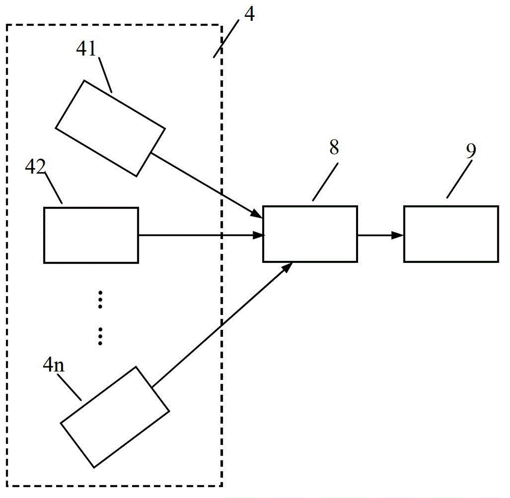
[0042] see figure 2 , similar to Embodiment 1, the difference is that n-level U-shaped tubes are connected in parallel to the frame 4 structure, and after n-level U-shaped tubes 41, 42, ..., 4n are connected in parallel, the n-level U-shaped tubes are connected in parallel The water flow in frame 4 is collected to the water flow collection pipe 8 connected in parallel with n-stage U-shaped pipes. As long as the diameter and mouth size of the n-level U-shaped pipes connected in parallel are appropriately increased, the collection of large water flows can be realized to meet the high-power power generation requirements of the power station 9; or for each U-shaped pipe in parallel Power stations 9 are respectively installed for multi-station grid-connected power generation to realize high-power power generation and power supply.

Embodiment 3

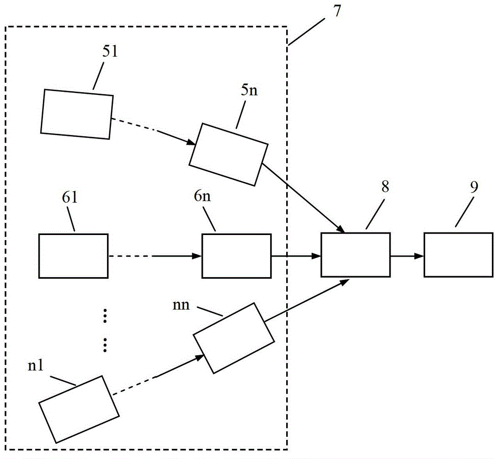
[0044] see image 3 , embodiment 3 is a combination of embodiment 2 and embodiment 1, the difference is that the n-level U-shaped tubes 51~5n, 61~6n, ..., n1~nn are arranged in a similar manner figure 1 The method for forming n-level U-shaped tubes is connected in series, and then the n-level U-shaped tubes 51~5n, 61~6n, ..., n1~nn are connected in a similar manner figure 2 The method is used to form a parallel connection to form a series structure of n-level U-shaped tubes and a parallel structure of n-level U-shaped tubes to form a mixed structure frame 7 . The water flow in the mixed structure frame 7 formed by the series structure of the n-level U-shaped tubes and the parallel structure of the n-level U-shaped tubes is collected to the water flow collection pipe 8 in which the n-level U-shaped tubes are mixed. As long as the diameter of the n-level U-shaped pipes connected in parallel is appropriately increased, the water collection pipe 8 can generate a domino effect to...


PUM


Abstract

The invention provides a hydraulic power generation system, relates to hydraulic power generation equipment, and provides the hydraulic power generation system capable of controllably changing the water current direction and flow in engineering technology methods such as a siphon principle, a gravity principle and a domino effect. The hydraulic power generation system comprises a water source, n levels of U-shaped pipes, a water turbine, a power generation machine, and an electricity transmission and control system. A water inlet of the first level of the U-shaped pipe is arranged 2 m below the water surface of the water source, and the diameter of a water inlet section of the first level of the U-shaped pipe is larger than that of a water outlet section of the first level of the U-shaped pipe. The diameter of the water inlet section of the second level of the U-shaped pipe is smaller than that of the water outlet section of the second level of the U-shaped pipe. Likewise, the n levels of the U-shaped pipes are sequentially connected, at least one level of the U-shaped pipe is provided with a water filling hole including a safe pressure relief valve. The water turbine is arranged in a water outlet section or a water outlet pipe of the nth level of the U-shaped pipe. The power generation machine is connected with the water turbine. The electricity transmission and control system is connected with the water turbine and the power generation machine. The number n of the levels of the U-shaped pipes is larger than or equal to 2.

Description

technical field [0001] The invention relates to hydroelectric power generation equipment, in particular to a hydroelectric power generation system which utilizes siphon principle and gravity to artificially controlly change the direction and flow of water flow. Background technique [0002] Electricity is one of the most important energy sources in people's life and production. With the rapid development of modern economy, the bottleneck of energy shortage has appeared. The development of thermal power has been eliminated in most developed countries in the world because of its serious pollution problems; therefore, nuclear power and hydropower have gradually become the main sources of electric energy in developed countries in the 20th century. Emerging countries are limited to varying degrees by insufficient energy supply in the process of economic development; China, as the largest developing country, also faces a serious shortage of energy supply in its development proces...

Claims


Application Information

Patent Timeline
IPC IPC(8): F03B13/00
Inventor 郑胜洪林育兹
Owner 郑胜洪
Why Eureka
Try Eureka