Rail vibration absorber

A vibration absorber and track technology, applied in the field of vibration reduction devices, can solve the problems of unstable performance, limited vibration reduction and noise reduction effect, scratches and damages from external objects, etc., and achieves high efficiency and stability in vibration reduction performance, significant vibration reduction effect, and prolonged The effect of the service life

Active Publication Date: 2013-10-09
CHINA RAILWAY DESIGN GRP CO LTD +1
View PDF12 Cites 35 Cited by
  • Summary
  • Abstract
  • Description
  • Claims
  • Application Information

AI Technical Summary

Problems solved by technology

However, it has been found in engineering applications that elastic elements such as rubber are generally used in existing technical solutions, and then built-in mass blocks in the elastic elements, and rail transit is widely distributed and the external environmental conditions vary widely, long-term direct exposure After being exposed to the external environment, the physical properties of rubber and other elastic materials are easily affected by the external environment, and are also easily scratched and damaged by external objects, which will adversely affect the vibration and noise reduction performance and service life of the tuned shock absorber.
In addition, due to the small constraint force formed by the rubber-like elastic element on the mass block, the tensile and compressive components generated by the mass block on the elastic element during the movement inside the elastic element are large, and the shear component is small, so effective shear energy dissipation cannot be achieved. , the damping effect is also greatly limited
In addition, limited by the structure and materials, the applicable frequency range of this type of tuned damper for rails is small. For example, for low frequency control, the elastomer needs to have high elastic...

Method used


Image

  • Rail vibration absorber
  • Rail vibration absorber
  • Rail vibration absorber

Examples


Embodiment 1

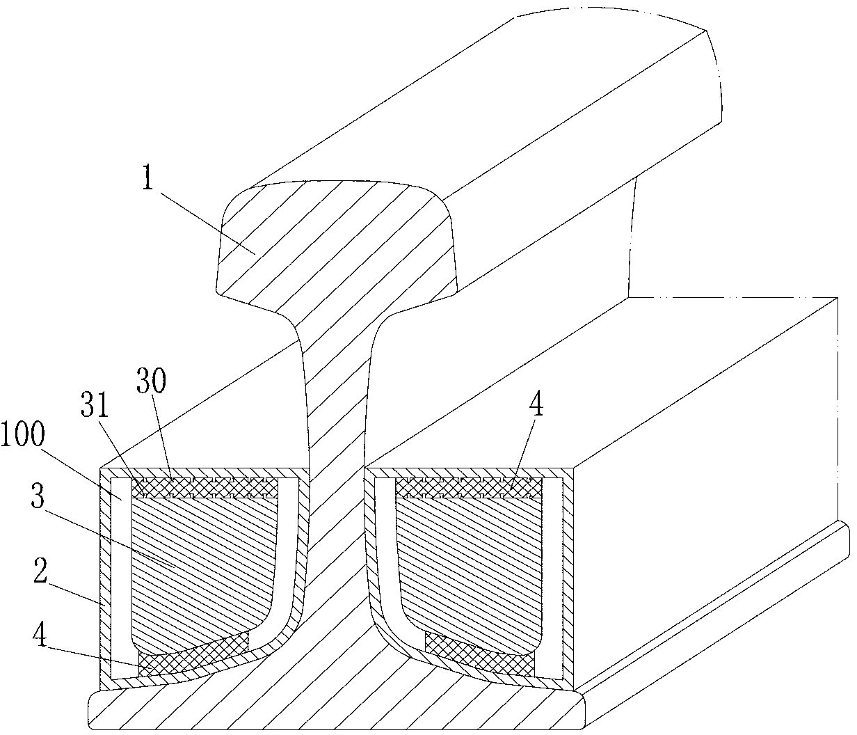
[0057] like figure 1 The rail shock absorber of the present invention as shown includes an elastic element 4 and a mass block 3, and also includes a coupling frame 2. The surface shape of the coupling frame 2 and the rail 1 flange and the rail waist coupling part is the same as that of the corresponding surface of the rail. The coupling frame 2 includes a vibration-absorbing cavity 100 , the mass block 3 is arranged in the vibration-absorbing cavity 100 of the coupling frame 2 , and an elastic element 4 is arranged between the mass block 3 and the wall of the vibration-absorbing cavity 100 . Specifically, the elastic element 4 is vertically arranged between the mass block 3 and the wall of the vibration-absorbing cavity 100 along the rail, the coupling frame 2 is made of aluminum alloy material, and the elastic element 4 is made of rubber material, because the rubber material has good damping It is a commonly used elastic solid damping material, so the elastic element 4 is als...

Embodiment 2

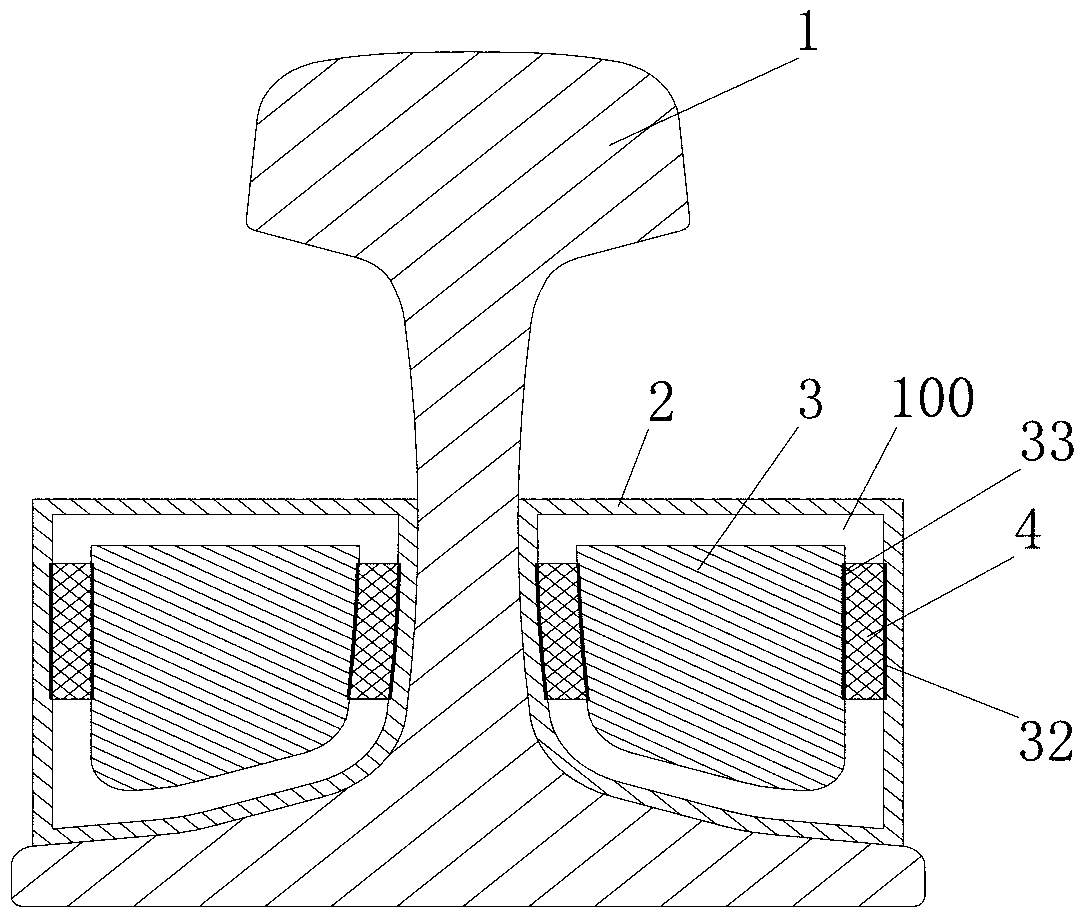
[0073] like figure 2The rail vibration absorber of the present invention shown differs from Embodiment 1 in that the elastic element 4 is arranged between the mass block 3 and the vertical cavity wall surface of the vibration-absorbing cavity 100 corresponding to the rail 1, and the coupling frame 2 is made of glass fiber reinforced plastic material, elastic The element 4 is made of high-damping elastic polyurethane material, and the mass block 3 is made of steel material, wherein the elastic element 4 is fixedly connected with the mass block 3 and the wall of the vibration-absorbing cavity 100 through chemical bonding process. In order to increase the reliability of the connection between the elastic element, the coupling frame and the mass block, a connection strengthening structure is respectively provided on the mating surface of the coupling frame and the elastic element and the mating surface of the mass block and the elastic element. The connection strengthening structu...

Embodiment 3

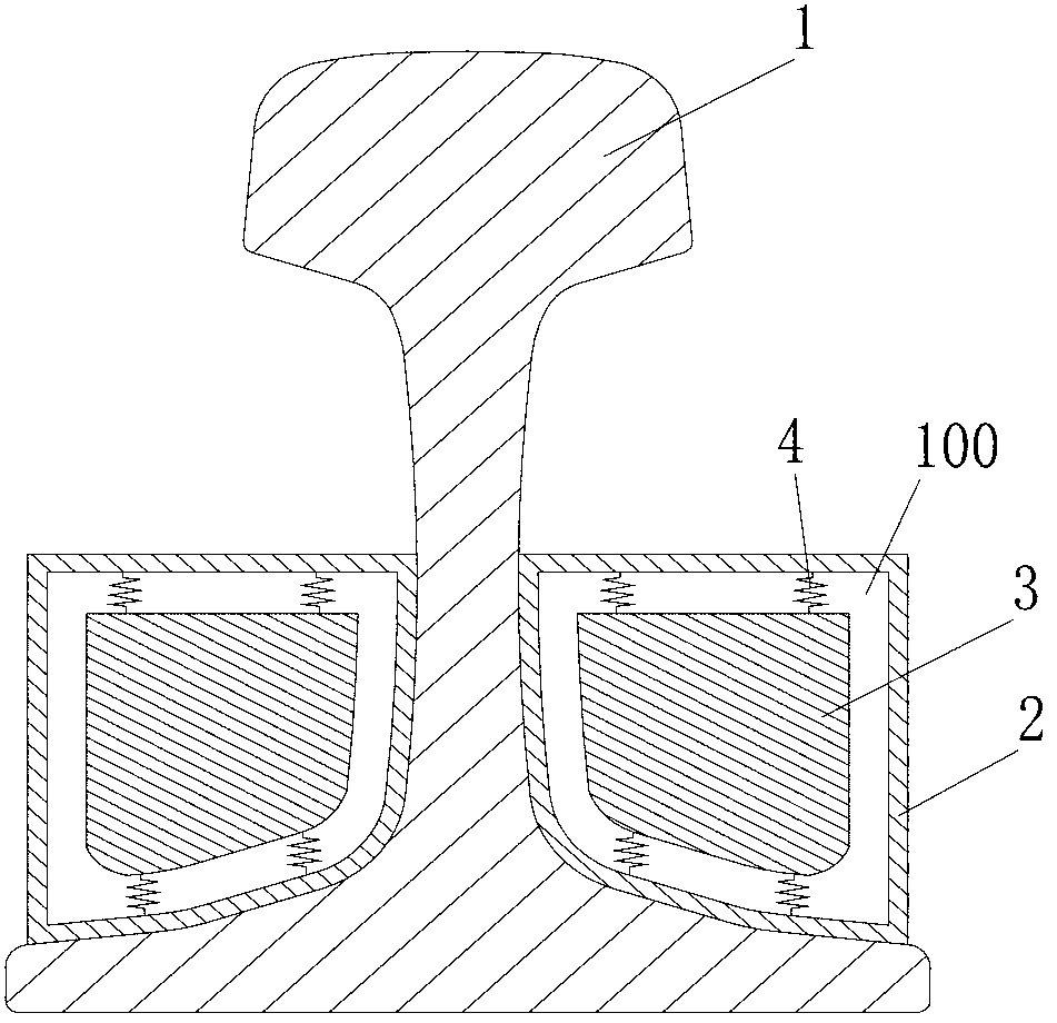
[0078] Such as image 3 The difference between the rail vibration absorber of the present invention shown in Embodiment 1 is that the coupling frame 2 is made of steel, and the elastic element 4 is arranged between the mass block 3 and the wall surface of the vibration-absorbing cavity 100 corresponding to the transverse direction of the rail 1. The elastic element 4 A metal spring is adopted, specifically a helical steel spring in this example, and the two ends of the helical steel spring are respectively welded and fixed on the connection frame 2 and the mass block 3 . In addition, in order to ensure that the elastic element 4 always forms an effective support for the mass block 3 during use, the elastic element 4 is pre-compressed when it is assembled with the mass block 3 and the coupling frame 2, and is in a pre-compressed state, and the elastic element 4 The pre-compression displacement is greater than the vibration amplitude of the mass block 3 relative to the wall of t...


PUM


Abstract

The invention discloses a rail vibration absorber which comprises an elastic element, a mass block and at least one connection framework. The connection framework is the same as the surface of a steel rail non-working surface connection part in shape. The connection framework comprises at least one vibration absorption cavity. At least a part of the mass block is arranged in the vibration absorption cavity of the connection framework. The elastic element is arranged between the mass block and the cavity wall of the vibration absorption cavity. The rail vibration absorber has the advantages that due to the fact that a mass-spring system composed of the mass block and the elastic element is arranged in the connection framework, the mass block and the elastic element are effectively protected by the connection framework; the mass block is only connected with the elastic element in series so that the material selection range of the elastic element can be wide; the space occupied by the elastic element is small, so that a larger and heavier mass block is arranged under the same condition, and the quality tuning vibration reducing effect is achieved; the rail vibration absorber is simple in structure, stable in performance, good in weather resistance, wide in application frequency domain, long in service life, superior in cost-performance ratio, beneficial to delaying abrasion to a steel rail and prolonging the service life of the steel rail, and very wide in market application prospect.

Description

technical field [0001] The invention belongs to the field of vibration and noise control of rail traffic, and in particular relates to a vibration damping device arranged on a non-working surface of a rail and used to reduce the vibration and noise generated by the rail during rail vehicle operation. Background technique [0002] In recent years, the rapid development of my country's rail transit has provided people with a fast and safe way of travel. At the same time, the vibration and noise problems generated by it have also seriously affected the quality of life of surrounding residents, endangered the safety of surrounding buildings, and made the track itself stable. Safety, safety and service life are also affected. [0003] Research shows that among the railway noise generated during train operation, wheel-rail noise accounts for a high proportion, and the contribution of medium and high-frequency noise radiated by rail vibration to the final total noise is particularly...

Claims


Application Information

Patent Timeline
IPC IPC(8): E01B19/00
CPCE01B19/003F16F7/108E01B5/02E01B19/00
Inventor 李洪尹学军孙海富孔祥斐郭郦曲洪啸徐鹏付学智
Owner CHINA RAILWAY DESIGN GRP CO LTD
Why Eureka
Try Eureka