

Mobile phone antenna with reconfigurable directional diagram
A mobile phone antenna and pattern technology, applied to the antenna, radiation element structure, electrical components, etc., to achieve the effects of high efficiency, small SAR value, and convenient processing
- Summary
- Abstract
- Description
- Claims
- Application Information
AI Technical Summary
Problems solved by technology
Method used
Image

Examples
Embodiment 1
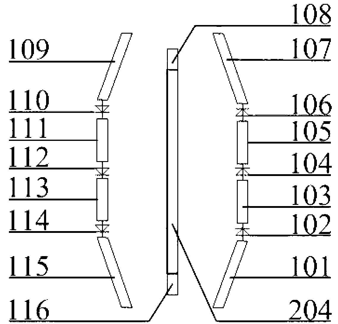
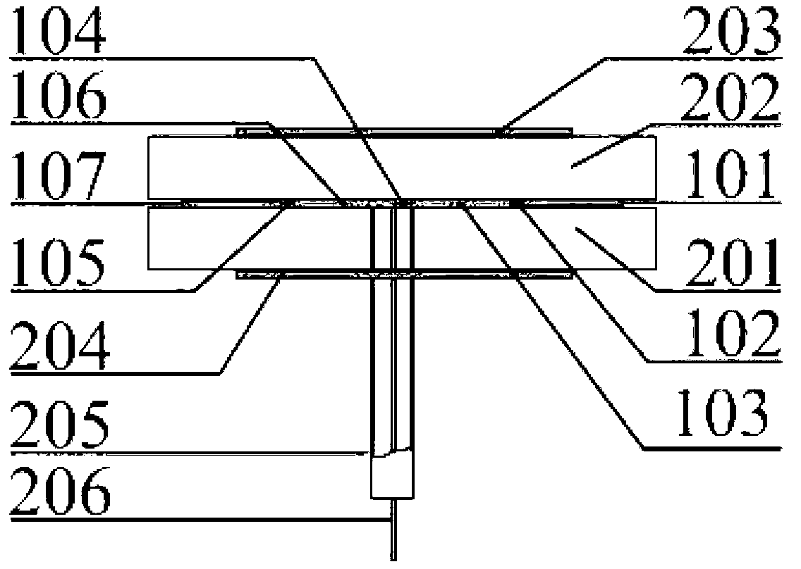
[0037] An example of the directional pattern reconfigurable mobile phone antenna involved in the present invention is as figure 1 and figure 2 shown. The antenna consists of dielectric substrates (201, 202), bent passive vibrators (101, 107, 109, 115), horizontal straight passive vibrators (103, 105, 111, 113), RF-PIN switches (102, 104 , 106, 110, 112, 114), dipole excitation oscillators (108, 116), vertical parasitic oscillators (203, 204), balancer (205) and coaxial feeder (206). The side view of the antenna is as figure 2 shown, where 101 and 107 are figure 1 Right bent passive vibrator, 103 and 105 figure 1 The right straight passive oscillator, 102 and 104 are figure 1 The PF-PIN switch on the right side, 205 is a balancer, and 206 is a coaxial feeder. according to figure 1 and figure 2 As shown in the structure, as long as the appropriate size is selected, it can meet the requirements of pattern reconstruction and wide frequency impedance bandwidth.
[0038]...
Embodiment 2
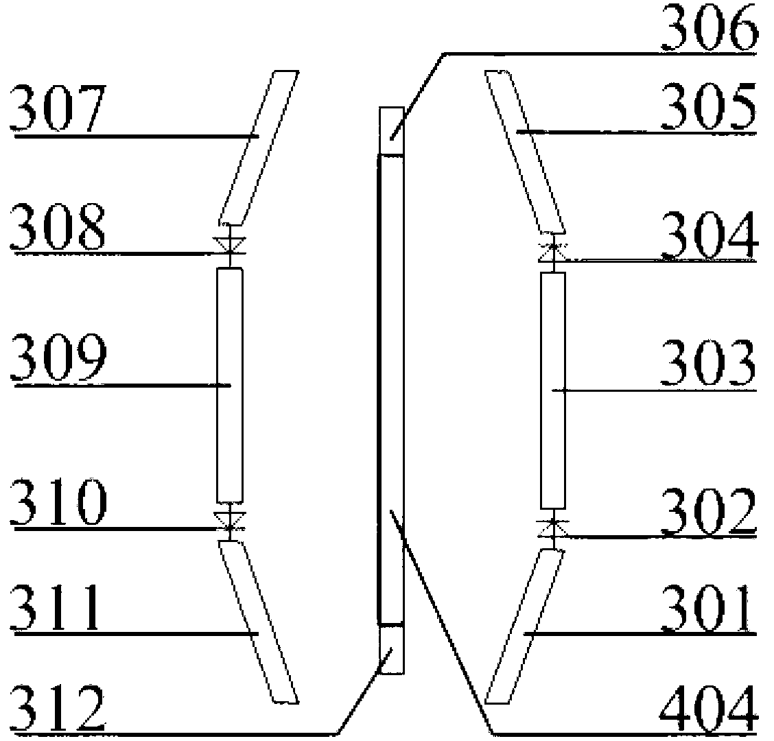
[0040] Such as image 3 and Figure 4 As shown, another implementation example of the present invention is to remove the RF-PIN switch on the basis of implementation example 1. By adjusting the bending angle of the bent passive dipole and the distance between the passive dipole and the active dipole dipole, the impedance bandwidth and pattern gain of the antenna can be adjusted so that the designed antenna can meet the required communication requirements. The antenna consists of dielectric substrates (401, 403), bent passive vibrators (301, 305, 307, 311), horizontal straight passive vibrators (303, 309), RF-PIN switches (302, 304, 308, 310 ), a dipole excitation oscillator (306, 312), a vertical parasitic oscillator (404, 405), a balancer (406) and a coaxial feeder (407). according to figure 1 and figure 2 The structure shown, as long as the size is appropriate, can meet the demand for pattern reconstruction of the narrowband frequency band.
Embodiment 3
[0042] Such as Figure 5 and Figure 6 As shown, another implementation example of the present invention is to design a reconfigurable antenna with a pattern using only horizontal straight passive dipoles, dipole excitation dipoles and RF-PIN switches. The radiating element of the antenna can be designed using Yagi antenna theory and pattern reconfigurable antenna theory. The antenna consists of dielectric substrates (601, 602), bent passive oscillators (501, 507, 509, 515), horizontal straight passive oscillators (503, 505, 511, 513), RF-PIN switches (502, 504 , 506, 510, 512, 514), dipole excitation vibrator (508, 516), balancer (603) and coaxial feeder (604). according to Figure 4 As shown in the structure, as long as an appropriate size is selected, it can meet the requirements of the pattern reconstruction of the narrowband frequency band.
PUM
 Abstract
Description
Claims
Application Information