Low-melting-point alloy casting positioning technology in turbine blade machining

A steam turbine blade, low melting point technology, applied in positioning devices, metal processing equipment, metal processing machinery parts, etc., can solve the problems of increased product materials and processing time, inability to use clamping methods, large processing deformation, etc., to achieve saving The effects of time and raw materials, good mechanical properties, and small design standard errors

Active Publication Date: 2013-10-16
常州市三维技术成套设备有限公司
View PDF7 Cites 32 Cited by
  • Summary
  • Abstract
  • Description
  • Claims
  • Application Information

AI Technical Summary

Problems solved by technology

[0004] For some blade roots with toothed or other curved surfaces, it is impossible to process them by adding a process head on the end surface of the blade root
When the blade root is processed and formed, if the machined air passage (airfoil) is used as the processing basis, a considerable amount of processing material needs to be added to the air passage, and more machining allowance needs to be removed in the subsequent air passage processing. This will result in an increase in the product material and processing time, and the deformation of the processing will become larger
[0005] In the prior art, such as Chinese patents CN101767233B and CN102091919B, both methods waste a lot of raw materials. At the same time, when processing the middle part of the blade, constant correction is required, and the positioning method is unstable.

Method used


Image

  • Low-melting-point alloy casting positioning technology in turbine blade machining
  • Low-melting-point alloy casting positioning technology in turbine blade machining

Examples


Embodiment Construction

[0036] The present invention will be further described below in conjunction with the accompanying drawings and embodiments.

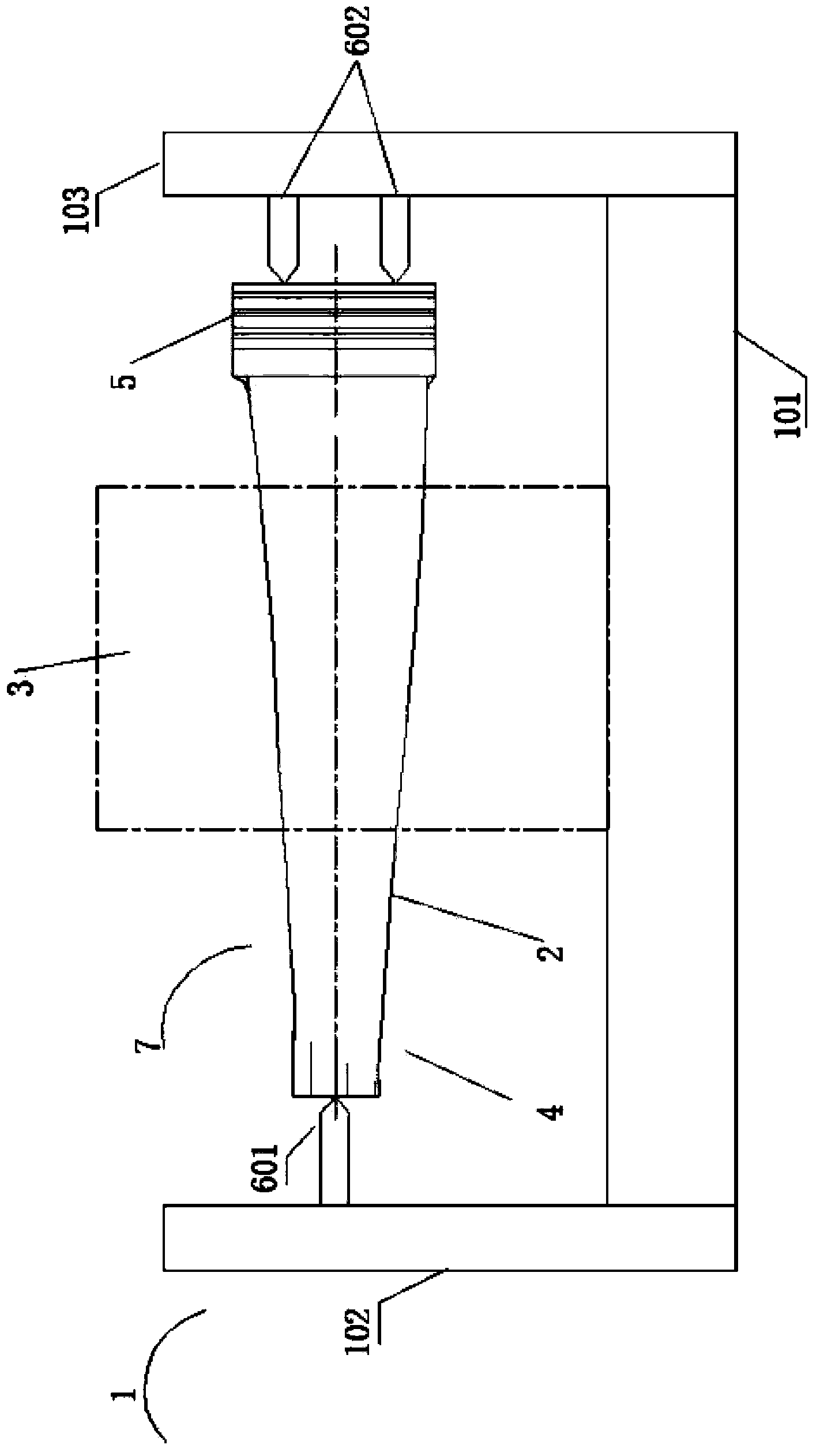
[0037] like figure 1 , is a schematic diagram of the assembly of the positioning tool, the positioning box and the blade of the present invention, the positioning tool 1 has a bottom plate 101, two vertical column plates 102 and 103, a single top 601, a double top 602, and the blade crown 4 conflicts with the single top 601 , the blade root 5 conflicts with the double apex 602. It can be seen that the center of gravity of the isosceles triangle formed by the straight line where the single apex 601 and the double apex 602 are located can basically coincide with the center of gravity of the blade 7, forming the most stable triangular positioning. The blade steam channel 2 passes through the positioning square box 3 .

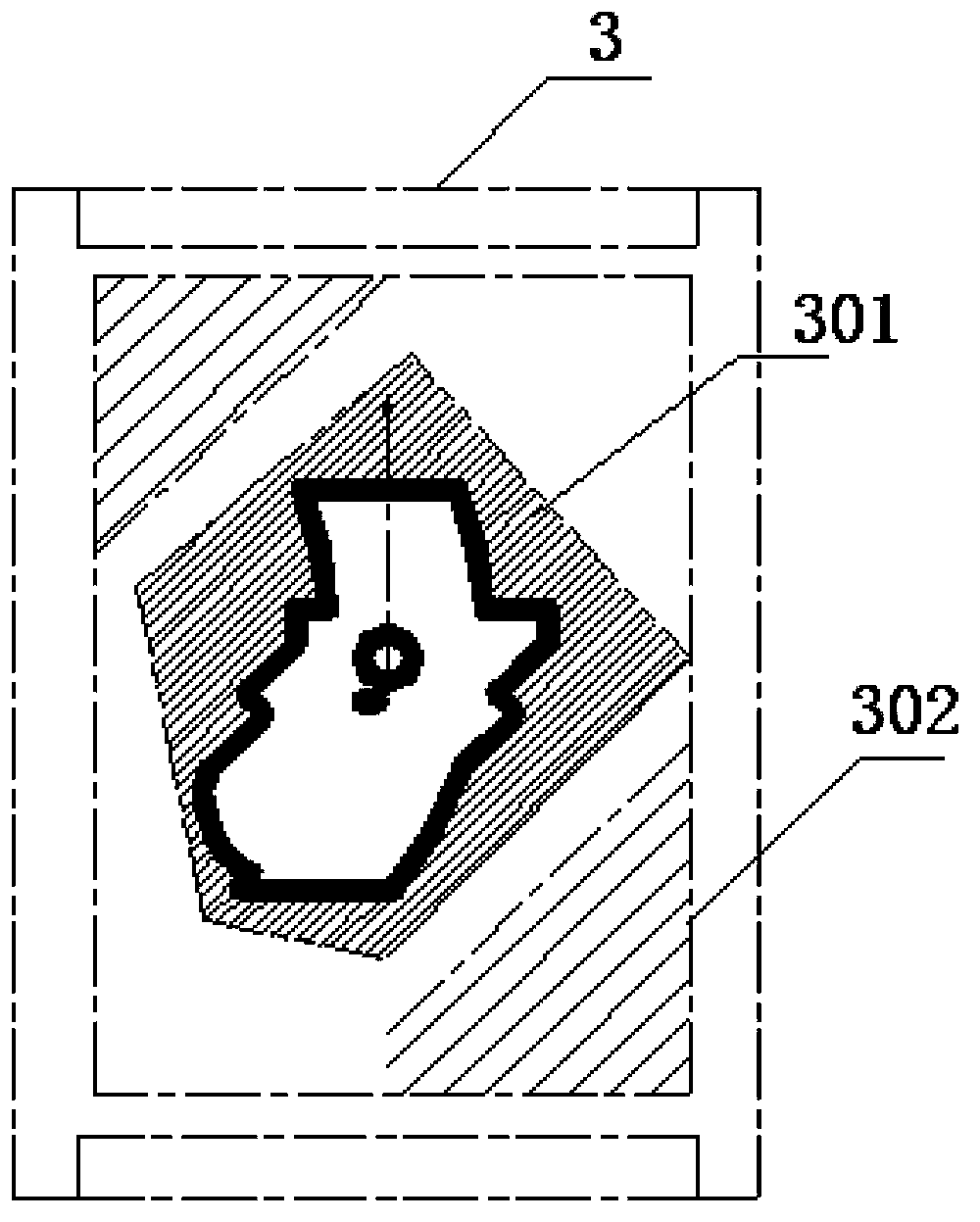
[0038] like figure 2 , is a side sectional view of the positioning square box, and the positioning square box 3 has a cavity 301 and a ...


PUM


Abstract

The invention discloses a low-melting-point alloy casting positioning technology in turbine blade machining. The low-melting-point alloy casting positioning technology is achieved through the following steps: (1) conducting rough machining on a blade; (2) matching the blade with a positioning tool, wherein the blade is transversely arranged after the rough machining on the blade is completed, a blade crown at the head of the blade is abutted against a single tip of the positioning tool, a blade root at the tail of the blade is abutted against double tips of the positioning tool, and a blade steam passage in the middle of the blade penetrates through a positioning square box; (3) casting tin-bismuth alloy molten liquid molten at a certain temperature in the positioning square box, and casting and cooling the positioning square box at the same time until tin-bismuth alloy is solidified and fixed; (4) conducting fine machining on the blade crown and the blade root; (5) melting the tin-bismuth alloy again, pouring out the tin-bismuth alloy molten liquid from the positioning square box, and removing the positioning square box; (6) conducting fine machining on the blade steam passage. The low-melting-point alloy casting positioning technology in the turbine blade machining can meet the requirements for machining blades of various shapes and sizes, the positioning effect is good, and raw materials are greatly saved.

Description

technical field [0001] The invention relates to a low-melting-point alloy casting and positioning process in the processing of steam turbine blades, and belongs to the technical field of finishing of steam turbine impellers. Background technique [0002] The steam turbine blade is an important part of the steam turbine. The processing technology and precision of the blade affect the working efficiency of the steam turbine to a large extent. The strength of the blade also plays an important role in the safety and maintenance of the steam turbine. The design of twisted blades with variable cross-section has become more and more common. At the same time, as the power of the unit increases, the blades are made longer and longer. The increase of the height of the blade will cause the problem of insufficient rigidity when the blade is processed. The blade processing technology must solve the above problems. [0003] The steam turbine blade is sequentially composed of three parts...

Claims


Application Information

Patent Timeline
Patent Type & Authority Applications(China)
IPC IPC(8): B22D19/00
CPCB23Q3/086B23Q3/063
Inventor 刘明刘小忠
Owner 常州市三维技术成套设备有限公司
Why Eureka
Try Eureka