

Metal part additive manufacturing method based on contour features
A metal parts, additive manufacturing technology, applied in the field of metal parts additive manufacturing based on contour features, can solve the problems of low quality, high equipment cost, low material utilization rate, etc., to achieve low cost, good labor conditions, and efficiency. high effect
- Summary
- Abstract
- Description
- Claims
- Application Information
AI Technical Summary
Problems solved by technology
Method used
Image

Examples
example 1
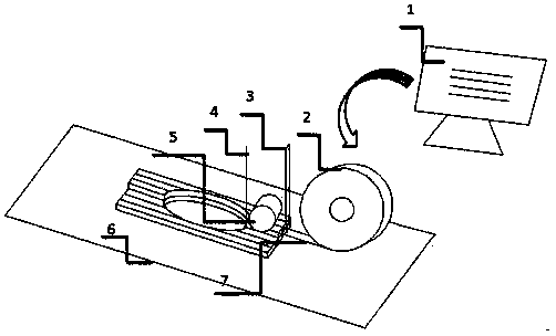
[0041] Example 1: a figure 1 The shown method of additive manufacturing of metal parts based on curved profile features
[0042] Part manufacturing for this constant-width single-track curved profile feature:
[0043] 1. Establish the CAD geometric model of the metal part and extract the STL model of the part;
[0044] 2. The width of the metal part model is 6.5mm and the length is 100mm. Considering that there is a certain blank margin, you can choose to send out a sheet with a width of 7mm; according to the design of the resistance welding process, use a metal sheet with a thickness of 2mm, which can be Parts with good morphology, structure and mechanical properties are obtained. Therefore, a metal sheet with a width of 7 mm and a thickness of 2 mm is used as the welding raw material.
[0045]3. The contour point set of the STL model is extracted and filled by the layered slicing software, and a G code containing manufacturing information such as feeding thickness 2mm and...
example 2
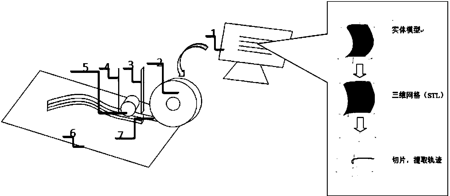
[0049] Example 2, a figure 2 The metal part manufacturing method based on part entity manufacturing shown
[0050] For the manufacture of this kind of metal part with a hole in the middle and a wide width:
[0051] 1. The outer contour of the metal part model is 50mm in width, 100mm in length, and the diameter of the middle hole is 40mm. Establish the CAD geometric model of the metal part and extract the STL model of the part;
[0052] 2. Use a metal sheet with a width of 10mm and a thickness of 1mm as the welding material.
[0053] 3. According to the STL model and the width and thickness of the raw material, the contour point set of the STL model is extracted and filled by the layered slicing software to generate a G code that can be recognized by the machine tool. This G code can control the movement of the workbench according to the planned part manufacturing path, that is, first control the completion of the single-layer multi-channel manufacturing of the entire part p...
Embodiment 3
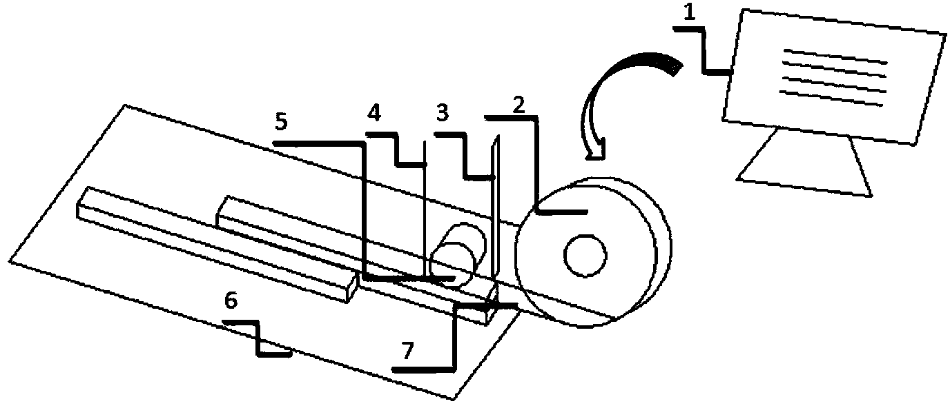
[0062] Embodiment 3: a kind of image 3 The metal part manufacturing method based on part entity manufacturing shown
[0063] For the manufacture of such metal parts with local bosses:
[0064] 1. The outer contour of the metal part model is 24mm in width, 150mm in total length, 50mm in length at both ends, and 12mm in width. Establish the CAD geometric model of the metal part and extract the STL model of the part;
[0065] 2. Use a metal sheet with a width of 12mm and a thickness of 3mm as the welding material.
[0066] 3. According to the STL model, as well as the width and thickness of the raw material, the contour point set of the STL model is extracted and filled by the layered slicing software, and a G code that can be recognized by the machine tool is generated.
[0067] The G code can control the movement of the workbench according to the planned part manufacturing path, that is, first control the completion of the single-layer multi-channel manufacturing of the enti...
PUM
| Property | Measurement | Unit |
|---|---|---|
| Thickness | aaaaa | aaaaa |
| Width | aaaaa | aaaaa |
| Length | aaaaa | aaaaa |
Abstract
Description
Claims
Application Information