a drilling system

A drilling and coiled tubing technology, which is applied to the automatic control system of drilling, drilling equipment, drill pipe, etc., can solve the problems of operator safety hazards, low rigidity, poor electrical characteristics and anti-interference ability, etc., and achieves strong anti-interference ability. , The effect of high transmission rate and long transmission distance

Active Publication Date: 2015-08-12
SICHUAN HONGHUA PETROLEUM EQUIP
View PDF9 Cites 0 Cited by
  • Summary
  • Abstract
  • Description
  • Claims
  • Application Information

AI Technical Summary

Problems solved by technology

[0012] (3) Composite coiled tubing 02 has low impact resistance;
[0013] (4) The temperature resistance of most composite materials is lower than 100??C;
[0014] (5) The stiffness of coiled tubing 02 made of composite material is lower than that of steel coiled tubing, and the drilling capability is limited;
[0015] (6) Once the composite coiled tubing 02 is damaged, it is very difficult to repair
[0016] In addition, the patent uses a cable as the information transmission channel between the ground and the bottom of the well. The cable is a transmission medium with a relatively narrow transmission frequency band, and its electrical characteristics and anti-interference ability are poor; at the same time, the power of the ground power supply 05 of the drilling device is After being transformed by the ground power transformer 07, it is transmitted to the downhole, and then the downhole power is transformed by the downhole power transformer 011 and then sent to the measurement mechanism 015, the guide tool 016, the electric control thruster 014, the electric control disconnector 013 and the electric motor 018 , it is troublesome to connect the power transformer 011 underground, which increases the workload and brings safety hazards to the operators

Method used


Image

  • a drilling system
  • a drilling system
  • a drilling system

Examples


Embodiment Construction

[0042] Below in conjunction with accompanying drawing, the present invention is described in detail.

[0043] In order to make the object, technical solution and advantages of the present invention clearer, the present invention will be further described in detail below in conjunction with the accompanying drawings and embodiments. It should be understood that the specific embodiments described here are only used to explain the present invention, not to limit the present invention.

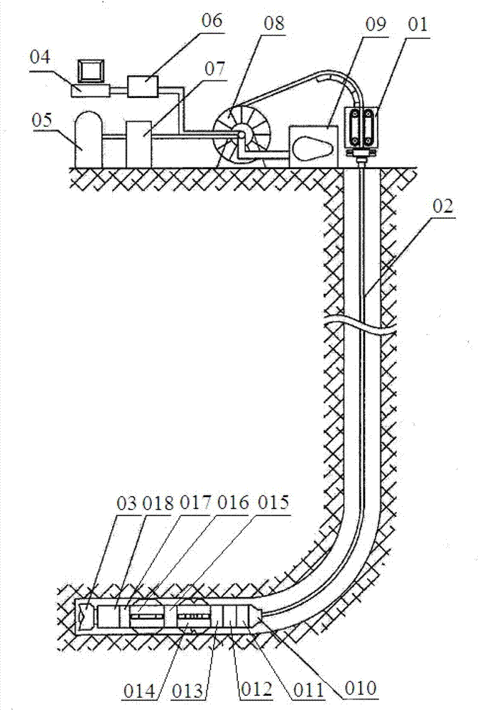
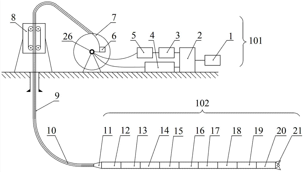
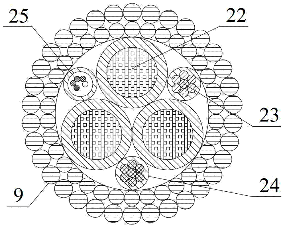
[0044] Such as figure 2 , 3 , 4, the coiled tubing intelligent electric drilling system includes a ground control system 101, a lower drilling tool 102, and a coiled tubing 9 connecting the ground control system 101 and the lower drilling tool 102; wherein the coiled tubing 9 is provided with a photoelectric composite cable 10 The photoelectric composite cable 10 includes a three-phase power cable 22, a power cable 23, a signal cable 24, and an optical fiber cable 25. The photoelectric composit...


PUM


Abstract

A drilling system, comprising a ground control system (101), a coiled tubing (9) and a lower drilling tool (102), wherein a photoelectric composite cable (10) is arranged in the coiled tubing, and the photoelectric composite cable comprises a three-phase power cable (22), a power supply cable (23), a signal cable (24) and an optical fibre cable (25) therein; the ground control system comprises an injection head (8), a ground photoelectric converter (6), a PLC control module (2), a roller (7), a rectifier inverter (3), a booster transformer (5) and a ground information processing module (4); and the lower drilling tool comprises a connector (11), a cable head nipple (12), a non-rotating joint (13), a remote transmission nipple (14), an electric disconnection and circulation nipple (15), a drilling parameter measurement nipple (16), an inclination azimuth measurement nipple (17), an electric motor (18), an electric guiding nipple (19), a near drill bit measurement nipple (20) and a drill bit (21) which are connected in sequence. By injecting the photoelectric composite cable into the coiled tubing to establish a ground and underground well power and information passage, the drilling system overcomes the defects of the composite coiled tubing, and can achieve the electrification and intelligentization of drilling with the coiled tubing by mating the existing coiled tubing and the device.

Description

technical field [0001] The invention relates to oil and gas drilling equipment, in particular to a drilling system. Background technique [0002] Oil and gas drilling is an underground concealed project, especially when drilling complex structure wells and special process wells under complex geological conditions, there are a lot of heterogeneity, uncertainty, non-structural, and non-numerical problems. To solve the "black box" problem of drilling, it is urgent to apply information technology and intelligent control technology to drilling engineering. [0003] How to establish the power and signal channel between the surface and the bottom of the well during the drilling process is the key to realizing automatic and intelligent drilling. In terms of signal transmission, currently commonly used signal transmission methods include mud pulse transmission, electromagnetic wave transmission and acoustic wave transmission. Among them, the most widely used mud pulse has the disad...

Claims


Application Information

Patent Timeline
Patent Type & Authority Patents(China)
IPC IPC(8): E21B7/00E21B44/00E21B47/12E21B47/00
CPCE21B19/22E21B7/068E21B17/206
Inventor 张弭单代伟王信君邓果姚宇翔胡晓君夏宏克
Owner SICHUAN HONGHUA PETROLEUM EQUIP
Why Eureka
Try Eureka