Casting system used for twin-roll thin strip continuous casting and use method thereof

A twin-roll thin-strip continuous casting and casting system technology, applied in the thin-strip continuous casting field, can solve problems such as affecting the smooth production of product quality, unfavorable renewal of molten steel in the upper part of the molten pool, reducing the impact force of turbulent flow strands, etc. The effect of reducing the transition package, simplifying the structure and reducing the impact force of the stream

Active Publication Date: 2013-10-23
NORTHEASTERN UNIV
View PDF10 Cites 9 Cited by
  • Summary
  • Abstract
  • Description
  • Claims
  • Application Information

AI Technical Summary

Problems solved by technology

[0004] The patent application with the application number 200720012995.9 discloses a flat structure submerged distribution nozzle suitable for continuous casting of thin slabs. The molten steel outlet of the nozzle has five molten steel outlet holes, of which the two symmetrical lower tapping holes and the bottom surface of the nozzle are The vertically downward central tap hole is relatively large, so this type of nozzle is not suitable for thin strip continuous casting; the patent application with application number 200520012263.0 discloses a four-hole special-shaped submerged cloth nozzle suitable for thin slab continuous casting It also has the same characteristics; the patent application No. 02283420.6 discloses a special-shaped flow distributor for thin strip continuous casting. The flow out of the distribution hole at the bottom of the flow device is not conducive to the renewal of the molten steel in the upper part of the molten pool, and the liquid surface of the molten pool is easy to crust; the patent application with the application number 01276402.7 discloses a distributor and a distribution device. The distributor is not immersed in the flow distribution device. The molten steel falls into the flow distributor, and the flow distributor does not have a device to reduce the impact force of the turbulent stream, which will easily cause the molten steel to flow unstable in the flow distributor, and then cause the distribution flow to be uneven, resulting in liquid in the molten pool Surface fluctuations are intensified, and the temperature in the molten pool is uneven, which affects product quality and even smooth production

Method used


Image

  • Casting system used for twin-roll thin strip continuous casting and use method thereof
  • Casting system used for twin-roll thin strip continuous casting and use method thereof
  • Casting system used for twin-roll thin strip continuous casting and use method thereof

Examples


Embodiment 1

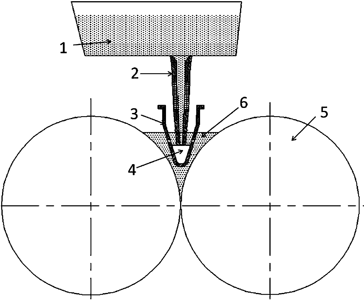
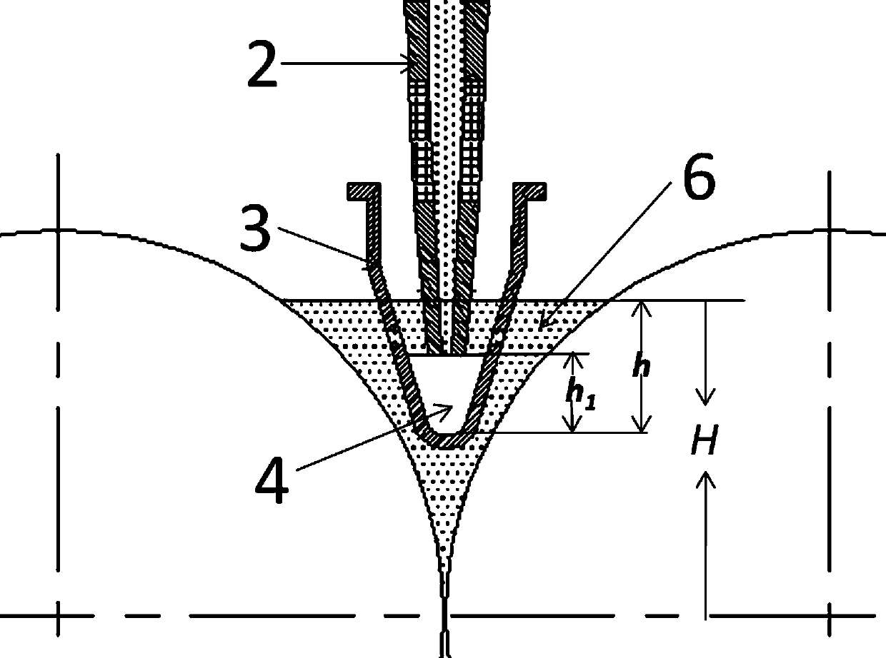
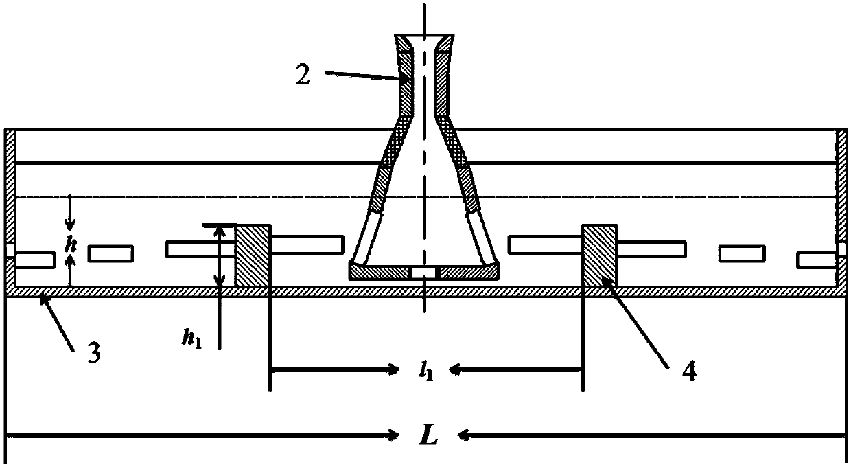
[0054] The casting system structure for twin-roll thin strip continuous casting is as follows: figure 1 As shown, the partial enlarged picture is shown in figure 2 As shown, including the submerged distribution outlet 2 and the flow distributor 3, the structure is as follows image 3 Shown; the structure of the submerged cloth outlet 3 is as follows Figure 4 As shown, the A-A section diagram is shown in Figure 5 As shown, it is composed of an inflow section 7, a transition section 8 and a flat outflow section; the outflow section is divided into two parts: a constriction section 9 and an expansion section 10 from top to bottom;

[0055] The shrinkage rate of the cross-sectional area of ​​the shrinkage section 9 is 30%, that is, the bottom cross-sectional area of ​​the shrinkage section 9 S 3 than the cross-sectional area of ​​the top of the contraction section 9 S 2 30% smaller, the expansion angle between the width direction of the contraction section 9 and the vert...

Embodiment 2

[0071] The structure of the casting system for twin-roll thin strip continuous casting is the same as in Embodiment 1, the difference is that:

[0072] (1) The expansion section is provided with a narrow surface tapping hole 11 on the two side walls of the narrow surface, and a wide surface tapping hole 12 on the two side walls of the wide surface; the structure is as follows Figure 6 shown; the upper edge of the wide face tap hole 12 is equal to or lower than the upper edge of the narrow face tap hole 11; the cross-sectional area of ​​each narrow face tap hole S 1 is the cross-sectional area of ​​the bottom end of the constriction S 3 75% of the horizontal diversion angle α Between 175°; the cross-sectional area of ​​each wide face tap hole is the cross-sectional area of ​​each narrow face tap hole S 1 15% of

[0073] (2) The structure of flow distributor 3 is as follows: Figure 9 As shown, each wide surface distribution hole 14 is distributed in a step shape from th...

Embodiment 3

[0076] The structure of the casting system for twin-roll thin strip continuous casting is the same as in Embodiment 1, the difference is that:

[0077] (1) The shrinkage rate of the cross-sectional area of ​​the shrinkage section is 15%, the expansion angle between the width direction of the shrinkage section and the vertical plane is 25°, and the convergence angle between the length direction of the shrinkage section and the vertical plane is 2°;

[0078] (2) The expansion angle between the width direction of the expansion section and the vertical plane is 10°, and the convergence angle between the length direction and the vertical plane is 5°;

[0079](3) The cross-sectional area of ​​each narrow taphole in the expansion section is 50% of the cross-sectional area at the bottom of the contraction section, and the horizontal diversion angle is 175°; the cross-sectional area of ​​the bottom taphole is that of the narrow taphole 5% of the cross-sectional area;

[0080] (4) The ...


PUM

PropertyMeasurementUnit
thicknessaaaaaaaaaa
heightaaaaaaaaaa
heightaaaaaaaaaa

Abstract

The invention relates to a casting system used for twin-roll thin strip continuous casting and a use method thereof, and belongs to the technical field of thin strip continuous casting. The system comprises a submerged flow distribution water gap and a flow distributor, wherein the submerged flow distribution water gap consists of an inflow section, a transition section and an outflow section; the outflow section is divided into a contraction section and an expansion section from top to bottom; and the expansion section is in a fan-shaped and wedge-shaped flat shape and is provided with steel outlets. A use method comprises the steps that the submerged flow distribution water gap and the flow distributor are arranged under a tundish; liquid steel flows into the submerged flow distribution water gap, enters the flow distributor, and enters the gap between two casting rolls from flow distribution holes in the flow distributor; and the two casting rolls are started to move in opposite directions, the liquid level of a molten bath is kept to be higher than the upper edge of each steel outlet and each flow distribution hole, and the liquid steel is formed into thin strip steel after being cast-rolled by the casting rolls. Two times of flow distribution are realized for the liquid steel by the fan-shaped and wedge-shaped flat expansion section, the multi-hole flow distributor and flow guide dams of the multi-hole flow distributor, the fluctuation of the liquid steel level is reduced, and the smooth going of a cast rolling process and the quality of thin strips are guaranteed.

Description

technical field [0001] The invention belongs to the technical field of thin strip continuous casting, and in particular relates to a casting system for twin-roll thin strip continuous casting and an application method thereof. Background technique [0002] Twin-roll thin strip continuous casting is a new process that uses a set of counter-rotating casting rolls and side sealing plates as a crystallizer to directly produce 1~6mm thick strip steel with liquid steel; compared with traditional continuous casting processes, it has a shorter process , low production cost, energy saving and environmental protection; in addition, because the liquid metal undergoes plastic deformation while solidifying, and completes the transition from liquid to solid thin strip in a short time, the solidified structure of the cast strip is dense, which improves the cast strip. mechanical properties. [0003] The twin-roll thin strip continuous casting process is a casting and rolling process that ...

Claims


Application Information

Patent Timeline
Patent Type & Authority Applications(China)
IPC IPC(8): B22D11/06
Inventor 陈敏董建宏王楠
Owner NORTHEASTERN UNIV
Why Eureka
Try Eureka