Eureka AIR delivers breakthrough ideas for toughest innovation challenges, trusted by R&D personnel around the world.

A thin-layer culture polygeneration system

An aquaculture system and polyproduction technology, which is applied in the field of thin-layer aquaculture polyproduction system, can solve the problems of difficulty in realizing polyproduction, poor vertical mixing, and low space utilization rate, etc. Strength requirements, the effect of light weight

Active Publication Date: 2015-08-19
ENN SCI & TECH DEV
View PDF7 Cites 0 Cited by
  • Summary
  • Abstract
  • Description
  • Claims
  • Application Information

AI Technical Summary

Problems solved by technology

[0006] The purpose of the present invention is firstly to solve the problems of low space utilization rate (the space between the culture surface and the ground is not utilized), difficulty in realizing polygeneration, large depth of liquid layer, poor mixing in the vertical direction, etc. existing in the prior art, Propose a Thin Layer Culture Polygeneration System

Method used


Image

  • A thin-layer culture polygeneration system
  • A thin-layer culture polygeneration system
  • A thin-layer culture polygeneration system

Examples


Embodiment 1

[0077] Such as image 3 As shown, in this embodiment, the bottom surface 1 is made of EVA shed film, which is attached to the first support beam 3-1 and tightened to form the cultivation device. The bottom surface 1 is rectangular, with a total length of 50 meters and a width of 10 meters. It is arranged obliquely along the supporting frame 3, and its high end is 3 meters away from the ground, and its low end is 2 meters away from the ground. The first support beam 3-1 is laid along the short side of the bottom surface 1 (that is, laid horizontally, perpendicular to the flow direction of the algae liquid), with a distance of 0.5 meters. The longitudinal load-bearing beam 3-2 is located under the first support beam 3-1 and along the bottom surface 1. Lay in the long side direction (that is, lay vertically, parallel to the flow direction of the algae liquid), with a spacing of 2.5 meters; set up 3-3 door-shaped supports at the bottom, with a spacing of 10 meters. The door supp...

Embodiment 2

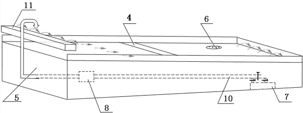
[0082] Such as Figure 4 As shown, in this embodiment, the bottom surface 1 is made of EVA shed film and is rectangular in shape with a total length of 100 meters and a width of 20 meters. In the middle of the bottom surface 1 (at 50 meters), there is an air replenishment tank 4 (10cm deep), and a microporous air replenishment pipe is set in the air replenishment tank 4, which is continuously fed with CO 2 For the gas of the component, the longitudinal load beam 3-2 at 4 places of the gas supply tank is disconnected. The high end of bottom surface 1 is 3.5 meters away from the ground, and the low end is 2 meters away from the ground. With the gas-liquid mixing pump as the power input device, the main valve is opened, the branch valve connected to the buffer tank 7 is closed, and the CO 2 Mixed gas with air (where CO 2 Concentration is 3%) fully contact with the algae liquid at the gas-liquid mixing pump to provide carbon source for the growth of microalgae. Cover film 2 is...


PUM

PropertyMeasurementUnit
angleaaaaaaaaaa
depthaaaaaaaaaa
thicknessaaaaaaaaaa

Abstract

The invention relates to a thin-layer breeding multiple production system. The multiple production system comprises a thin-layer breeding system and a greenhouse system, wherein the thin-layer breeding system comprises a breeding device and a circulatory system; the breeding device comprises a bottom surface and a corresponding support frame; the breeding device is in a closed loop connection with the circulatory system; and the greenhouse system is disposed below the breeding device. The support frame of the thin-layer breeding system, as a main structure body of the greenhouse system, combines the thin-layer breeding system and the greenhouse system, so that plant and animal breeding can be developed while carrying on microalgae breeding, thereby realizing stereoscopic and resourceful utilization of land and providing novel mode for developing ecology energy and ecological agriculture.

Description

technical field [0001] The invention relates to a polygeneration system for thin layer culture. Background technique [0002] Photosynthetic microorganisms / plant cells can use solar energy, water and simple minerals to synthesize organic matter and inorganic matter in the form of hydrogen, oxygen, methane, etc. Microalgae are a kind of individual micro-photoautotrophic / combined-trophic, unicellular / simple multicellular organisms, which have the characteristics of wide distribution, various types, high photosynthetic efficiency, fast growth rate, and strong adaptability. [0003] Large-scale and high-yield cultivation is the bottleneck restricting the development of microalgae industrialization. The development of low-cost and high-efficiency cultivation system is the key to the large-scale production of microalgae. At this stage, three-dimensional photobioreactors still generally have problems such as high cost and difficulty in scaling up. At present, many enterprises cont...

Claims


Application Information

Patent Timeline
Patent Type & Authority Patents(China)
IPC IPC(8): C12M1/00
Inventor 朱振旗王琳崔洪亮程小雪桑俊宝卢彦兴
Owner ENN SCI & TECH DEV
Why Eureka
Eureka Blog
Learn More