Communication method of immersion liquid transmission system applied to immersion lithography machine

A technology of immersion lithography and transmission system, which is applied in the direction of transmission system, microlithography exposure equipment, photoplate making process exposure device, etc., to achieve the effect of ensuring accuracy, improving degree of freedom, and improving controllability

Inactive Publication Date: 2013-11-13
ZHEJIANG UNIV
9 Cites 3 Cited by

AI-Extracted Technical Summary

Problems solved by technology

[0005] In order to solve the communication problem between the control subsystem and the water treatment subsystem, the transmission control subsystem, and the pose adjustment subsystem in the immersio...

Abstract

The invention discloses a communication method of immersion liquid transmission system applied to an immersion lithography machine. The transmission system comprises a control subsystem, which is taken as the server; a water process subsystem, which is taken as the client terminal; a transmission control subsystem and a position adjusting subsystem. A network topology construction is formed between the control subsystem, the water processing subsystem, the transmission control subsystem and the position adjusting subsystem, and the data exchange is carried out through the Ethernet. The server/client terminal mode is adopted, a virtual communication relationship is established between the control subsystem, the water processing subsystem, the transmission control subsystem and the position adjusting subsystem, each virtual communication relationship is provided with a virtual communication link, and each virtual communication link maintains the session between a pair of nodes. The communication of the control subsystem in the immersion liquid transmission system of an immersion lithography machine with other subsystems is achieved through the communication method, communication and information transmission functions are effectively achieved, and thus high-efficient and sequent operation of the immersion liquid transmission system is achieved.

Application Domain

Technology Topic

Image

  • Communication method of immersion liquid transmission system applied to immersion lithography machine
  • Communication method of immersion liquid transmission system applied to immersion lithography machine
  • Communication method of immersion liquid transmission system applied to immersion lithography machine

Examples

  • Experimental program(1)

Example Embodiment

[0030] The specific implementation process of the present invention will be described in detail below in conjunction with the drawings and embodiments.
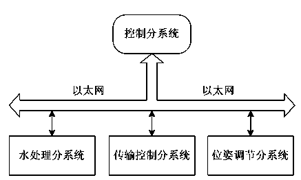
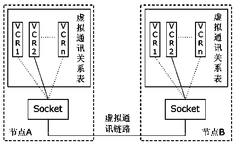
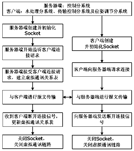
[0031] like figure 1 As shown, the immersion liquid transmission system includes the control subsystem as the server, the water treatment subsystem as the client, the transmission control subsystem and the posture adjustment subsystem; the control subsystem and the water treatment subsystem, the transmission control subsystem and the position adjustment subsystem. The attitude adjustment subsystems are constructed to form a network topology, and Ethernet is used for data exchange; the server/client mode is adopted to establish between the control subsystem and the water treatment subsystem, the transmission control subsystem and the attitude adjustment subsystem A virtual communication relationship establishes a virtual communication link for each pair of virtual communication relationships, and each virtual communication link maintains a physical session of a pair of nodes.
[0032] The network topology can adopt star structure, centralized structure, ring structure, bus structure or distributed structure.
[0033] The realization of the communication method is communication among multiple systems or between multiple modules of a system.
[0034] like Figure 5 As shown, it describes the operation mechanism of this communication method among multiple modules in a system. When information needs to be transmitted between modules A, B and C with independent functions, the virtual communication controller of the module uploads the communication information to In the clock control unit, the clock control unit comprehensively analyzes the communication information from different modules, and transmits the results to the virtual communication controller of each module, and then the virtual communication controller of the module controls the communication port for data transmission and data reception to realize different Effectiveness of information transfer between modules.
[0035] The function of the clock control unit is to receive the communication information of the virtual communication controller of each module, analyze it, and send the control system to the virtual communication controller of each module in a logical order, so as to coordinate the communication of each module in a logical order;
[0036] A module with independent functions must have the virtual communication controller of the module and the corresponding communication port. The function of the virtual communication controller of the module is to control the communication port of the module and to receive the control information with the clock control unit in a timely manner. and sending to ensure the validity of the communication; the function of the communication port is to realize the information communication with the target module through Ethernet.
[0037] The Ethernet protocol adopts TCP/IP or UDP/IP protocol.
[0038] like figure 2 As shown, the virtual communication relation (VCR, virtual communication relation) always exists in pairs between the two nodes of the Ethernet communication, and each pair of virtual communication relation represents a virtual communication link (VCL, virtual communication link). Each virtual communication link maintains a set of sessions between two physical Ethernet nodes. The virtual communication relationship is to send and receive messages by creating sockets (Socket) to realize data transmission, and different virtual communication relationships send and receive messages through different sockets.
[0039] like image 3 As shown, the virtual communication link maintaining a physical session of a pair of nodes includes the following steps:
[0040] (1) The server/client mode is adopted, the control subsystem is the server, the water treatment subsystem, the transmission control subsystem and the pose adjustment subsystem are the clients;
[0041] (2) The server creates a socket and initializes it, including binding port and IP address, etc.;
[0042] (3) The server starts to monitor the client's connection request;
[0043] (4) The client creates a socket and requests a connection to the server after initialization;
[0044] (5) After receiving the connection request from the client, the server verifies its IP address. If it is a known IP address, it accepts the request, and if it is an unknown IP address, it rejects the request;
[0045] (6) When the server and the client are successfully connected, the virtual communication link is opened, and the server and the client realize two-way data transmission and reception, including the transmission of instructions and files;
[0046] (7) When the client shuts down, the virtual communication link needs to be closed. The client sends a disconnection signal to the server, and then both parties close the socket, disconnect the virtual communication link, and end the communication.
[0047] The virtual communication link can not only realize the transmission of message data, but also realize the transmission of files.
[0048] The virtual communication link can be reconnected when the virtual communication relationship is accidentally disconnected, or an alarm can be given when the reconnection fails.
[0049]Each of the virtual communication links has a module for algorithmic verification of message data.
[0050] Figure 4 Describes the software operation mechanism for nodes to realize communication, such as Figure 4 As shown, each of the virtual communication links has a module for algorithmic verification of message data.
[0051] When sending data, the upper-layer application passes the data to the data verification module. If the verification is wrong, the data verification module notifies the upper-layer application. If the verification is correct, the data verification module transfers the data to the data transceiver module for packaging processing , and finally deliver the encapsulated data packet to the destination node through Ethernet;
[0052] When receiving data, the data transceiver module receives the data packet transmitted by the originating node, decompresses it, and transmits the decompressed data to the data verification module, and the data verification module performs algorithm verification on the decompressed data. If the verification is correct, the data will be handed over to the upper application; if the verification is incorrect, the upper application will be notified for processing.
[0053] At the same time, the abnormal scanning module monitors the data sending and receiving module in real time. If there is an abnormal situation in the communication, it will call the abnormal processing module to process it, and notify the upper layer application of the processing result.
[0054] The above specific embodiments are used to explain the present invention, rather than to limit the present invention. Within the spirit of the present invention and the protection scope of the claims, any modification and change made to the present invention will fall into the protection scope of the present invention.

PUM

no PUM

Description & Claims & Application Information

We can also present the details of the Description, Claims and Application information to help users get a comprehensive understanding of the technical details of the patent, such as background art, summary of invention, brief description of drawings, description of embodiments, and other original content. On the other hand, users can also determine the specific scope of protection of the technology through the list of claims; as well as understand the changes in the life cycle of the technology with the presentation of the patent timeline. Login to view more.

Similar technology patents

Motorcycle

Owner:HONDA MOTOR CO LTD

Classification and recommendation of technical efficacy words

  • Increase freedom
  • Improve controllability

Electric pressure pot

Owner:FOSHAN SHUNDE MIDEA ELECTRICAL HEATING APPLIANCES MFG CO LTD

Liquid level control system

InactiveUS20100126433A1Improve controllabilitySteam separation arrangementsFuel injection apparatusEngineeringControllability
Owner:MITSUBISHI HITACHIPOWER SYST LTD
Why Eureka
Try Eureka