
Standard floating pipe type hydroelectric generator

A hydroelectric generator, a standard type of technology, applied in the direction of ocean energy power generation, engine components, machines/engines, etc., can solve the problems of reduced efficiency, limited ability to adjust, unstable current voltage or frequency, etc., to meet the comprehensive use function , compact structure, and the effect of improving power generation efficiency

Active Publication Date: 2013-11-20
CHONGQING TONGLI INDAL
View PDF7 Cites 16 Cited by
  • Summary
  • Abstract
  • Description
  • Claims
  • Application Information

AI Technical Summary

Problems solved by technology

In addition, due to the change of the speed of the river, the speed and torque of the water wheel in the generator change, so the current voltage or frequency generated by the generator is unstable.
The quality of the entire power generation system fluctuates and the efficiency decreases
Therefore, it is necessary to change the water intake of the generator inlet pipe and the angle of the blades of the water wheel to adjust the water flow of different flow rates to produce a smooth impact on the water turbine; however, the ability of this adjustment is still relatively limited and cannot fully meet the actual needs, especially For example, the main engine of the floating tube hydroelectric generator needs to be placed completely underwater, and the adjustment of the flow volume is difficult to achieve the desired effect, which hinders the further improvement of power generation quality and efficiency

Method used


Image

  • Standard floating pipe type hydroelectric generator
  • Standard floating pipe type hydroelectric generator
  • Standard floating pipe type hydroelectric generator

Examples


Embodiment 1

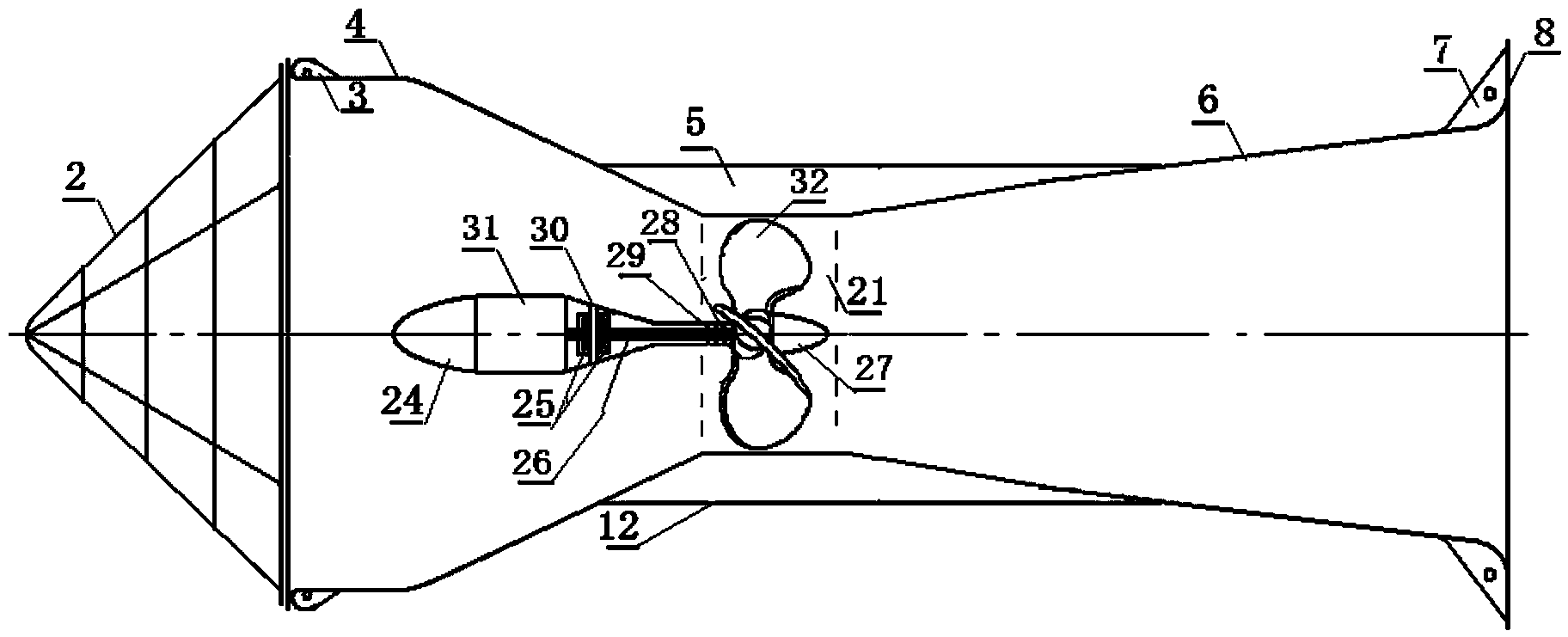
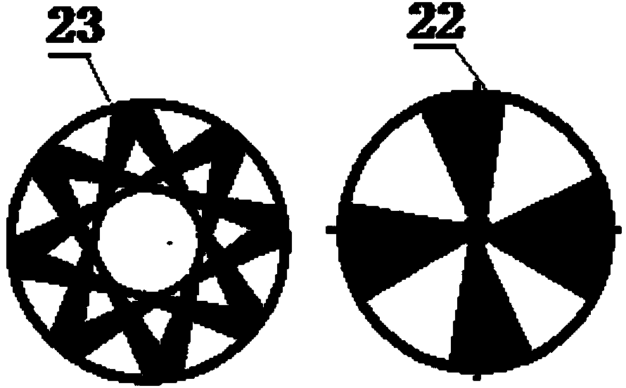
[0033] figure 1 The schematic diagram of embodiment 1 of the standard type floating tube hair type hydraulic motor provided by the embodiment of the present invention, image 3 A schematic diagram of a fan-shaped water turbine provided by an embodiment of the present invention, Figure 4 The schematic diagram of the paddle water turbine provided by the embodiment of the present invention is as shown in the figure: the standard floating tube generator provided by the present invention includes a floating tube speed increasing device, a water turbine, a generator, and the floating tube speed increasing device consists of a tubular water receiving device. It is composed of a device, a working section and a draft tube; the water turbine is arranged in the working section between the water outlet end of the tubular eliminator and the water inlet end of the draft tube, and the water turbine is connected to the generator.

[0034] The tubular water eliminator includes a straight sec...

Embodiment 2

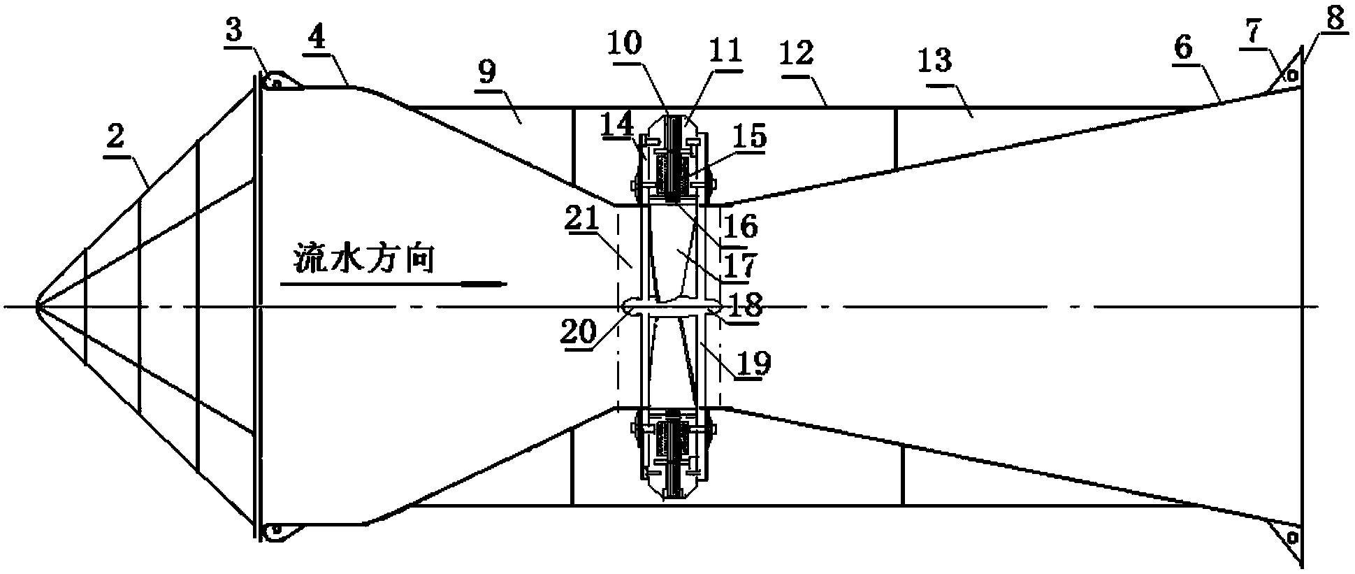
[0054] figure 2 The schematic diagram of Embodiment 2 of the standard floating tube type hydroelectric generator provided for the embodiment of the present invention, the difference between this embodiment and Embodiment 1 is only:

[0055] The water turbine is integrated with the generator, and there is almost no transmission device, so there is no transmission loss, which can achieve higher power generation efficiency. Determined according to the flow speed, the cross-sectional area of ​​the flow belt, the diameter of the water turbine, and the environmental protection requirements: choose the fan-shaped water wheel 22 or the polygonal water wheel 23 to achieve the best comprehensive effect.

[0056] Functions of other components: the slag blocking net 2 is used to block scum on the water and avoid it from blocking or winding the turbine to affect normal power generation; the front fixed ear 3 and the rear fixed ear 7 are used to connect anchor chains and cables in a single...

Embodiment 3

[0061]The standard floating tube generator hydraulic motor provided in this embodiment can be installed and used in the following ways:

[0062] The first way, such as Figure 7 As shown, multiple standard floating tube generators are integrated and installed as shown in the figure, and connected together to form a whole through the floating bridge 71 arranged on multiple standard floating tube generators, and floating bridges are set on both sides of the whole The pipe 70 links and supports the pontoon, and the water retaining plate 72 arranged under the pontoon can make the water flowing into the range of the integrated group fully play its role, and can play a role in improving efficiency; a movable hanger is also arranged on the pontoon, The hoisting hoist 74 is set on the movable hanger 73 to form a mobile quick-loading hoisting support, which makes installation and maintenance more convenient.

[0063] The second way, such as Figure 8 As shown, according to the instal...


PUM


Abstract

The invention discloses a standard floating pipe type hydroelectric generator which comprises a floating pipe accelerating device, a water turbine and a generator, wherein the floating pipe accelerating device comprises a tubular water collecting container, a work section and a draft tube; the water turbine is arranged in the work section between the water outlet end of the water collecting container and the water inlet end of the draft tube and connected with a motor. According to the standard floating pipe type hydroelectric generator, the tubular water collecting container of the floating pipe accelerating device is adopted to receive and collect a large area of slow running water, the power energy, pressure energy and potential energy of the tubular water collecting container can enable entered water flow to be supercharged and accelerated gradually, so that effluent water flow can spread rapidly; because of greater differential pressure of the front section and the rear section, the flow speed of the effluent water is increased greatly. Therefore, generating efficiency is improved, comprehensive use functions are met, the structure is compact, and the mounting and sealing are convenient.

Description

technical field [0001] The invention relates to a hydroelectric power generation device in the field of energy, in particular to a high-efficiency standard generator suitable for advection water. Background technique [0002] In the development and utilization of renewable clean energy technologies, wind power and photovoltaic power generation are limited by geographical conditions, and the installation and construction costs are also very high; hydroelectric power generation technology has received extensive attention; its principle is to realize hydroelectric power generation by acting on water wheels through flowing water ;Traditional hydropower generally includes water turbines, generators, pipelines and ancillary facilities, water pumps, power management, etc.; the construction of hydropower stations must have water flow and damming, the structure is relatively complicated, and resources are gradually in short supply. higher cost. Therefore, the construction of traditi...

Claims


Application Information

Patent Timeline
IPC IPC(8): F03B13/00
CPCF03B13/264F03B17/061F05B2240/133F05B2240/40F05B2240/93F05B2240/97Y02E10/30
Inventor 沈家同
Owner CHONGQING TONGLI INDAL
Learn More