Plasma thruster based on multilevel tip cusped magnetic field

A technology that can cut magnetic fields and plasma, applied in the field of ion propulsion, can solve the problems of low power density and short life of thrusters, and achieve the effect of avoiding space charge saturation effect, improving life and improving life.

Inactive Publication Date: 2013-11-20
HARBIN INST OF TECH
View PDF2 Cites 32 Cited by
  • Summary
  • Abstract
  • Description
  • Claims
  • Application Information

AI Technical Summary

Problems solved by technology

[0005] The present invention is to solve the short life of the existing thruster due to the serious sputtering corrosion of the ceramic wall by ions an

Method used


Image

  • Plasma thruster based on multilevel tip cusped magnetic field
  • Plasma thruster based on multilevel tip cusped magnetic field
  • Plasma thruster based on multilevel tip cusped magnetic field

Examples


specific Embodiment approach 1

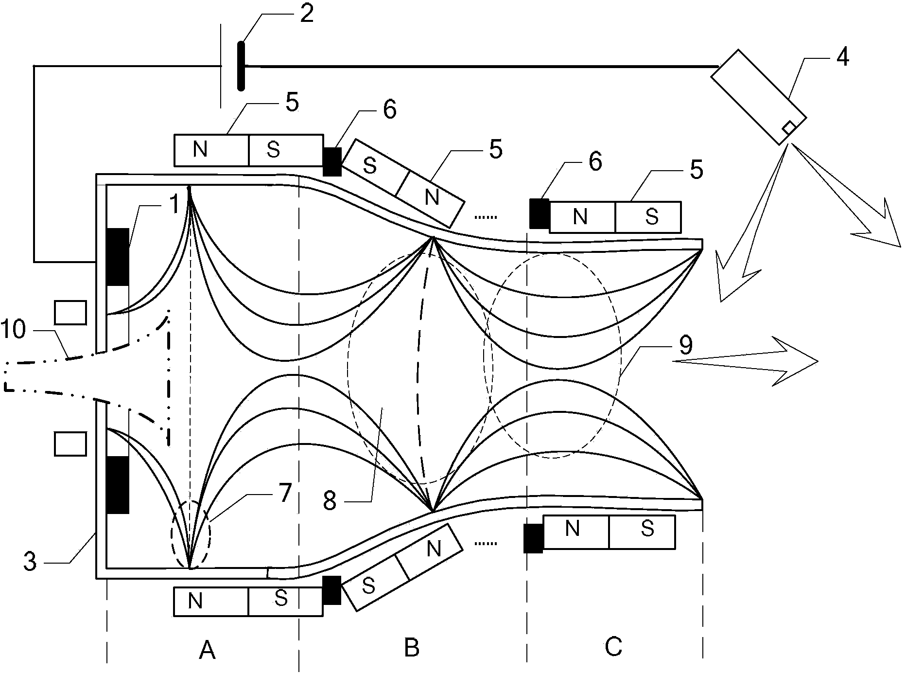
[0022] Specific implementation mode one: see figure 1 Describe this embodiment, a plasma thruster based on a multi-stage cusp magnetic field described in this embodiment, which includes an anode 1, a power supply 2, a circular ceramic cavity 3, a hollow cathode 4, and multiple circular rings permanent magnet 5, a plurality of magnetically permeable rings 6; the number of the circular permanent magnets 5 is greater than or equal to 3,

[0023] The bottom of the circular ceramic cavity 3 is provided with a working fluid jet hole, and an anode 1 is arranged around the working fluid jet hole,

[0024] The circular ceramic cavity 3 is divided into a front section A, a middle section B and a back section C along the emission direction of the working medium jet, the front section A is a barrel-shaped structure, and the middle section B is a circle with an isosceles trapezoidal axial section. Cylindrical structure, the rear section C is a cylindrical structure, and the inner diameter...

specific Embodiment approach 2

[0027] Specific implementation mode two: see figure 1 To describe this embodiment, the difference between this embodiment and the plasma thruster based on the multi-stage cusp magnetic field described in the first embodiment is that the number of the circular permanent magnets 5 is less than 15.

specific Embodiment approach 3

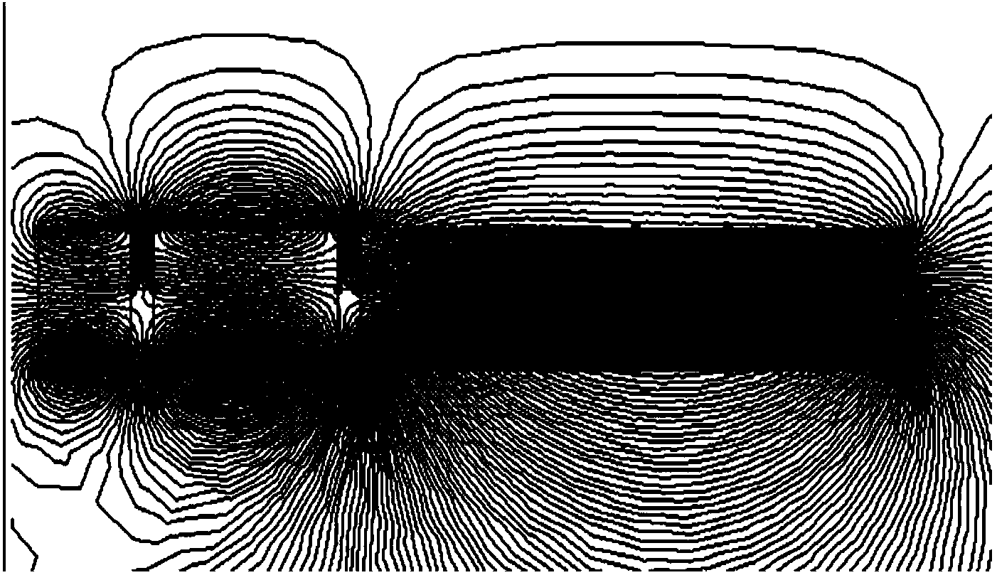
[0028] Specific implementation mode three: see Figure 4 Describe this embodiment, the difference between this embodiment and the plasma thruster based on the multi-stage cusped magnetic field described in the first or second embodiment is that the number of the circular permanent magnets 5 is equal to 3 .

[0029] In the present embodiment, the number of the annular permanent magnets 5 is equal to 3, which is a three-stage permanent magnet structure, and the three annular permanent magnets 5 are respectively socketed in the front section A, Outer side of midsection B and posterior section C. The confinement of electrons is mainly to be controlled by the oscillation of the tip magnetic mirror that forms the magnetic tip between adjacent two ring-shaped permanent magnets 5, and the periodic ring-shaped permanent magnet 5 can form a tangential magnetic field, and at the magnetic tip, the magnetic field mainly is the radial direction, electrons are effectively hindered due to t...


PUM


Abstract

The invention discloses a plasma thruster based on a multilevel tip cusped magnetic field, relates to the field of plasma thrusting, and aims to solve the problem that the service life is short due to serious sputtering etching of ceramic wall surfaces caused by ions and further solve the problem of low power density of a conventional thruster. The number of circular permanent magnets is larger than or equal to 3; a working medium jet flow hole is formed in the bottom of a circular ceramic cavity body; anodes are arranged on the periphery of the working medium jet flow hole; the inner diameter of the front section A of the circular ceramic cavity body is larger than that of the inner diameter of the rear section C; the side wall of the circular cavity body is sleeved with a plurality of circular permanent magnets sequentially; magnetizing directions of two adjacent circular permanent magnets are opposite; a magnetic conducting ring is fixed between every two adjacent circular permanent magnets; a positive pole of a power supply is electrically connected with the anodes; and a negative pole of the power supply is electrically connected a hollow cathode, and the hollow cathode is located on an outlet side of the circular ceramic cavity body. The plasma thruster is mainly applied to the aerospace field.

Description

technical field [0001] The present invention relates to the field of plasma propulsion. Background technique [0002] Electric propulsion has the advantages of high specific impulse, long life, compact structure, small size and light pollution, so it has gradually attracted the attention and favor of the aerospace industry. Among them, Hall thrusters and ion thrusters are currently the most widely used space electric propulsion devices. [0003] The Hall thruster uses inner and outer coaxial excitation coils to generate a mainly radial magnetic field, and ionizes and accelerates the plasma through a circular discharge channel to generate thrust. The disadvantage is that the thermal load on the inner wall is large and the temperature is high; the radial magnetic field cannot completely control the plasma beam, the sputtering corrosion of the ion on the ceramic wall is serious, and the life of the thruster is short. [0004] The ion thruster adopts the design of ion chamber ...

Claims


Application Information

Patent Timeline
IPC IPC(8): F03H1/00
CPCF03H1/0062
Inventor 孙国顺刘辉于达仁马成毓赵隐剑陈蓬勃
Owner HARBIN INST OF TECH
Why Eureka
Try Eureka