Method of cryogenic separation for light hydrocarbons on the basis of LNG (liquefied natural gas) cold energy

A technology for cryogenic separation and light hydrocarbons, which is applied in the field of cryogenic separation of light hydrocarbons based on LNG cold energy, and the separation of light hydrocarbon mixtures in refinery, which can solve the problems of large power consumption, save resources and reduce power consumption of compression , the effect of reducing energy costs

Inactive Publication Date: 2013-11-20
SOUTH CHINA UNIV OF TECH
View PDF3 Cites 18 Cited by
  • Summary
  • Abstract
  • Description
  • Claims
  • Application Information

AI Technical Summary

Problems solved by technology

The separation of ethylene cracking gas generally adopts the cryogenic separation method. The separation process require

Method used


Image

  • Method of cryogenic separation for light hydrocarbons on the basis of LNG (liquefied natural gas) cold energy
  • Method of cryogenic separation for light hydrocarbons on the basis of LNG (liquefied natural gas) cold energy
  • Method of cryogenic separation for light hydrocarbons on the basis of LNG (liquefied natural gas) cold energy

Examples


Embodiment 1

[0030] In this embodiment, a refinery dry gas separation is taken as an example, as follows:

[0031] The light hydrocarbons of a 12 million tons / year refinery mainly come from atmospheric and vacuum, catalytic cracking, delayed coking, hydrocracking, reforming and other devices. The light hydrocarbons of different components enter the dry gas pipeline network and are purified and dried by compressed alkaline washing Then, 78.23t / h, 15°C, 3.45MPa dry gas is obtained, and its composition (mass fraction) is shown in Table 1 below:

[0032]

[0033] Table 1 Composition of refinery dry gas

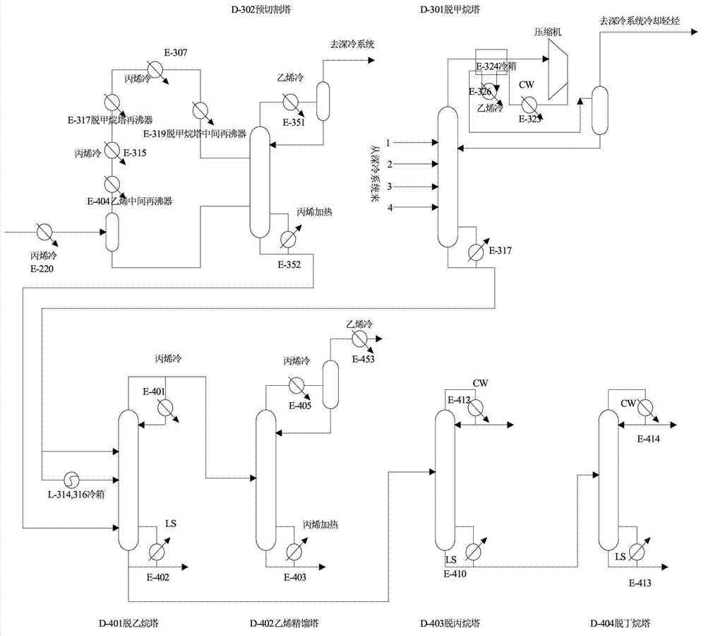
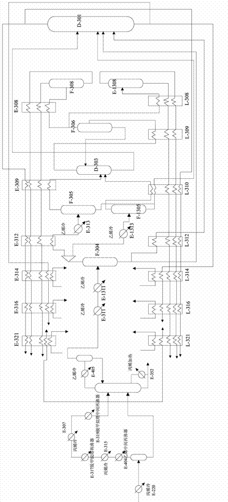
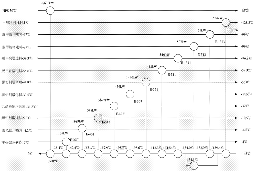
[0034] The cryogenic separation process of refinery dry gas is as follows: figure 1 with figure 2 As shown, the feed gas passes through the pre-cutting tower D-302 to separate light hydrocarbons above ethane from the bottom of the tower and then divides it into two streams into the de-ethanizer D-401. The top of the pre-cutting tower is discharged into the cryogenic system after cryogenic It is div...

Embodiment 2

[0043] This embodiment takes the separation of ethylene cracking gas as an example, as follows:

[0044] Taking the 400,000 t / a ethylene cracking gas separation process as an example, the cracking gas flow rate of the ethylene cracking unit is 97.75t / h. Its composition (mass score) is shown in Table 3:

[0045]

[0046] Table 3 Composition of ethylene cracking gas

[0047] The cryogenic separation process of ethylene cracking gas is as follows: Figure 4 with Figure 5 As shown, the ethylene cracking gas passes through the pre-cutting tower D-302 to separate light hydrocarbons above ethane from the bottom of the tower and then divides it into two streams into the de-ethanizer D-401, and the top discharge of the pre-cutting tower enters the cryogenic system for cryogenic cooling. After being divided into four strands, it enters the demethanizer D-301; the top output of the demethanizer is compressed and then enters the cryogenic system for deep cooling, and the bottom output of the d...


PUM


Abstract

The invention discloses a method of cryogenic separation for light hydrocarbons on the basis of LNG (liquefied natural gas) cold energy. The method includes: simulating to calculate cold energy allocation provided by a three-unit compression refrigerating system according to the traditional process of cryogenic separation for light hydrocarbons; determining according to the calculated cold energy and the actual conditions to use the cold energy provided by LNG to replace completely or partially the cold energy provided by the three-unit compression refrigerating system, thus determining usage of the LNG to obtain operation conditions of process flow of the cold energy that can be provided by the LNG in the traditional process of cryogenic separation for light hydrocarbons; according to operation conditions of a heat exchanger network using the LNG as a cold source and the process flow as a cold trap and according to Aspen Plus and Aspen Pinch simulation, synthetizing a heat exchanger network map, and determining the sequence of cold energy provision using the LNG as process flow; in the traditional process of cryogenic separation for light hydrocarbons, replacing completely or partially the three-unit compression refrigerating system with the LNG, and providing the cold energy to the process flow according to the sequence so as to complete the cryogenic separation of light hydrocarbons. The method has the advantages that compression refrigeration energy consumption in the process of light hydrocarbon separation can be saved and LNG gasification cost can be reduced.

Description

Technical field [0001] The invention relates to a method for separating light hydrocarbon mixtures in refining and petrochemical industries, in particular to a method for light hydrocarbon cryogenic separation based on LNG cold energy. It belongs to the field of light hydrocarbon mixture separation. Background technique [0002] Liquefied Natural Gas (LNG for short) is a low temperature liquid at -162°C. It needs to be gasified and heated to above 0°C before being supplied to downstream users. Most LNG receiving stations use open shelves The seawater vaporizer and submerged combustion vaporizer are used to heat and vaporize LNG. When 1.0t LNG is vaporized, approximately 230kWh of cold energy can be released, causing a great waste of energy. LNG cold energy can be used in processes such as air separation, power generation, cryogenic smashing, cold storage, light hydrocarbon separation, dry ice production, etc. If the cold energy of LNG is recycled, it can replace a large amount o...

Claims


Application Information

Patent Timeline
IPC IPC(8): F25J3/02
Inventor 李亚军罗浩
Owner SOUTH CHINA UNIV OF TECH
Why Eureka
Try Eureka