Ripple reducing circuit for light-load pulse hopping mode of DC-DC (Direct Current-Direct Current) converter

A converter and pulse-skipping technology, which is applied in the field of electronic circuits, can solve the problems of small output voltage ripple, large output voltage ripple, and high conversion efficiency, and achieve reduced output voltage ripple, peak value reduction, and high conversion efficiency effect

Active Publication Date: 2013-11-20
XIDIAN UNIV
View PDF6 Cites 20 Cited by
  • Summary
  • Abstract
  • Description
  • Claims
  • Application Information

AI Technical Summary

Problems solved by technology

The output voltage ripple of forced continuous mode is small and its frequency is constant in the whole load variation range, which is easy to filter out noise, but its light load efficiency is also the lowest
[0004] Generally speaking, the three working modes have their own advantages and disadvantages. In terms of efficiency, among the three light-load working modes, the burst mode has the highest light-load efficiency, followed by the pulse-skipping mode, and

Method used


Image

  • Ripple reducing circuit for light-load pulse hopping mode of DC-DC (Direct Current-Direct Current) converter
  • Ripple reducing circuit for light-load pulse hopping mode of DC-DC (Direct Current-Direct Current) converter
  • Ripple reducing circuit for light-load pulse hopping mode of DC-DC (Direct Current-Direct Current) converter

Examples


Embodiment 1

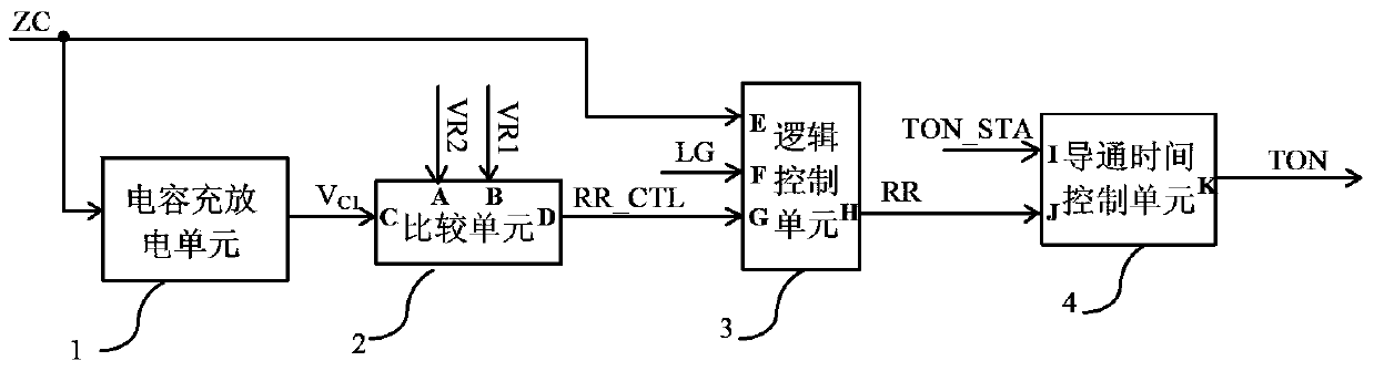
[0039] refer to figure 1 , the present invention is used in the ripple reduction circuit of DC-DC converter light load pulse skip mode, including capacitor charging and discharging unit 1, comparison unit 2, logic control unit 3 and on-time control unit 4. in:

[0040] Capacitor charging and discharging unit 1, according to the switch off signal ZC generated inside the converter, charges or discharges the capacitor to obtain voltage signals V of different sizes C1 output to comparison unit 2;

[0041] The comparison unit 2 has three input terminals A, B, C and one output terminal D; wherein the first input terminal A is connected to the reference voltage VR1 generated inside the converter, and the second input terminal B is connected to the reference voltage VR2 generated inside the converter , the third input terminal C is connected to the voltage signal V input by the capacitor charging and discharging unit 1 C1 ; Its output terminal D outputs the control signal RR_CTL to...

Embodiment 2

[0074] The capacitor charging and discharging unit 1 , the logic control unit 3 and the conduction time control unit 4 of the present invention are the same as those in the first embodiment.

[0075] refer to Figure 5 , the comparison unit 2 of the present invention includes two low-voltage PMOS transistors M 601 and M 602 , 3 low-voltage NMOS tubes M 603 ~ M 605 , 2 transmission gates TG 3 ~TG 4 , 2 inverters INV8~INV9;

[0076] The 2 transmission gates TG 3 ~TG 4 , its output terminal is connected and outputs the reference voltage V 2 , the third transmission gate TG 3 The input end of the converter is connected to the reference voltage VR1 generated inside the converter, and the fourth transmission gate TG 4 The input end of the converter is connected to the reference voltage VR2 generated inside the converter;

[0077] The low voltage PMOS tube M 601 and M 602 Form a differential pair structure, its source is connected and connected to the bias current I gene...

Embodiment 1 and Embodiment 2

[0082] In conjunction with embodiment 1 and embodiment 2, the working principle of the present invention is:

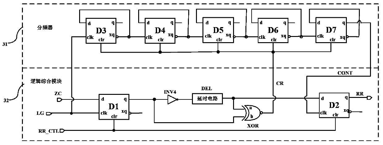
[0083] When the load of the converter is light, the converter works in skip cycle mode, the switching tube shutdown signal ZC is logic high level, and the first capacitor C inside the capacitor charging and discharging unit 1 1 start charging, the voltage signal V C1 Gradually increases, the voltage signal V C1 When it rises to the reference voltage VR1, the control signal RR_CTL output by the comparison unit 2 becomes a logic high level, and the frequency divider 31 starts counting the pulse signal LG of the lower switching tube of the converter. If the load is light enough, the frequency divider 31 counts After 16 cycles, the pulse counting signal CONT is turned to a high level, and the switch signal RR output by the logic synthesis module 32 is also turned to a logic high level at this time, and the conduction time control unit 4 is controlled to supply a large cu...


PUM


Abstract

The invention discloses a ripple reducing circuit for a light-load pulse hopping mode of a DC-DC (Direct Current-Direct Current) converter, which mainly solves the problem that the output ripple of an existing light-load pulse hopping mode is large. The ripple reducing circuit comprises a capacitance charge-discharge unit (1), a comparison unit (2), a logic control unit (3) and a switch-on time control unit (4), wherein the capacitance charge-discharge unit (1) is used for outputting different voltage signals VC1 according to difference of switch-off signals ZC of a switch tube; the comparison unit (2) is used for comparing the voltages signals with reference voltage and supplying a zero clearing signal to the logic control unit (3); the logic control unit (3) is used for counting a pulse signal LG and outputting a switch signal RR; the switch-on time of an upper switch tube can be controlled by the switch signal through controlling the size of charge current of internal capacitance of the switch-on time control unit (4), and a peak value of inductive current can be reduced. According to the ripple reducing circuit disclosed by the invention, the output voltage ripple of the light-load pulse hopping mode of the converter is effectively reduced while the high efficiency of the converter is ensured, and the ripple reducing circuit can be used for the DC-DC converter.

Description

technical field [0001] The invention belongs to the technical field of electronic circuits, and relates to an analog integrated circuit, in particular to a ripple reduction circuit for reducing the output voltage ripple of a step-down DC-DC converter in a light-load pulse-skipping mode. Background technique [0002] With the rapid development of the integrated circuit industry and the increasing expansion of the analog integrated circuit market, the application of power management chips is becoming more and more extensive. Its advantages of high efficiency, high integration, and light weight make it popular in portable electronic devices. With the continuous improvement of power management requirements, the power conversion in portable electronic equipment has gradually developed from the previous linear power supply to the switching power supply. The key components inside the switching power supply work in a high-frequency switching state and consume less energy, so the pow...

Claims


Application Information

Patent Timeline
IPC IPC(8): H02M1/15H02M3/00
Inventor 来新泉杨丽何全涛邵丽丽
Owner XIDIAN UNIV
Why Eureka
Try Eureka