
A Grazing Angle Reflection Infrared Spectroscopy Device with Controllable Temperature

A technology of infrared spectroscopy and angular reflection, applied in the field of grazing angle reflection infrared spectroscopy devices, can solve the problems of temperature measurement deviation, complicated steps, low thermal conductivity, etc., to avoid pollution and damage, realize program temperature control, and simple device structure. Effect

Inactive Publication Date: 2015-12-02
青岛小海智能科技有限公司
View PDF5 Cites 0 Cited by
  • Summary
  • Abstract
  • Description
  • Claims
  • Application Information

AI Technical Summary

Problems solved by technology

When the grazing angle reflection device in the prior art measures the sample, the contact temperature measurement methods such as thermocouples and thermal resistances usually used need to fix the temperature measurement point on the surface of the sample, which will easily cause damage to the sample and the substrate material when the sample is replaced. scratch damage, and the steps are cumbersome. The more serious problem is that the position where the infrared light is irradiated and the area where the light path passes are not allowed to be blocked by objects, so the temperature measurement point cannot be placed in the detection area, and the position of the temperature measurement point is biased. Shifting will cause large deviations in temperature measurement, so general temperature measurement methods cannot be applied to grazing angle reflection technology
For general heating devices and temperature measuring devices, the temperature measurement point is located inside the hot stage, and the sample film is close to the surface of the hot stage during the test. The temperature of the hot stage is basically the temperature of the sample, but for the grazing angle reflection infrared spectroscopy device In other words, since the substrate is glass with low thermal conductivity, there must be a temperature difference between the upper and lower surfaces of the substrate, so the surface temperature has a great relationship with the selection of temperature measurement points and temperature measurement methods, so the temperature of the sample cannot be accurately measured in the prior art , it is impossible to accurately control the temperature
For example, such as the grazing angle reflective infrared device of German Bruker (Bruker. Commercially available grazing angle reflective infrared devices such as reflective devices do not have the function of temperature control, and cannot realize low temperature measurement of samples

Method used

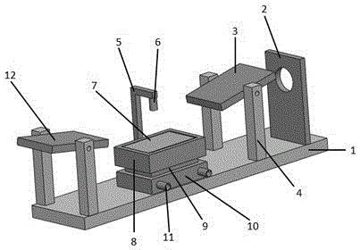
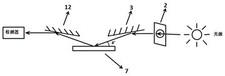

Image

  • A Grazing Angle Reflection Infrared Spectroscopy Device with Controllable Temperature
  • A Grazing Angle Reflection Infrared Spectroscopy Device with Controllable Temperature
  • A Grazing Angle Reflection Infrared Spectroscopy Device with Controllable Temperature

Examples


Embodiment 1

[0060] The crystallization behavior of polylactic acid (PLLA) was measured during heating and cooling.

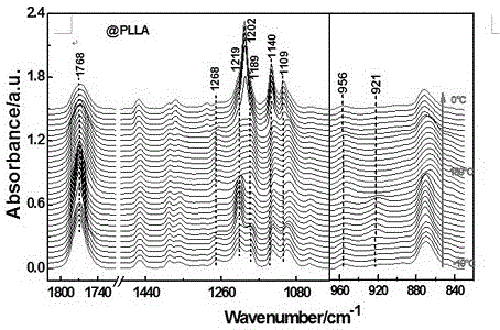
[0061] Place the substrate coated with polylactic acid (PLLA) samples on the hot stage, set the heating rate and set temperature through the temperature controller, start the cooling water and the cooling plate, and conduct infrared spectrum testing. image 3 It is the infrared spectrum change map measured when polylactic acid rises from minus 10 degrees Celsius at a heating rate of 2 degrees Celsius per minute to 180 degrees and then cools down to room temperature at a cooling rate of 2 degrees Celsius per minute. The scanning frequency is once per minute, but for Obviously observe the spectral changes of the sample during the heating process, and only select part of the spectrum for graphing. From the changes in the characteristic peaks in the figure, we can get the glass transition temperature Tg, crystallization temperature Tc, melting point Tm and other information of t...

Embodiment 2

[0063] Measurement of the crystallization behavior of poly-3-hexylthiophene (P3HT) during heating and cooling (continuous heating).

[0064] Place the substrate coated with poly-3-hexylthiophene (P3HT) sample on the hot stage, set the heating rate and set temperature through the temperature controller, start the cooling water and the cooling plate, and conduct the infrared spectrum test. Figure 4 and Figure 5 (a) is the infrared spectrum change graph measured after poly-3-hexylthiophene rises from minus 10 degrees Celsius to 200 degrees Celsius at a heating rate of 2 degrees Celsius per minute, and the scanning frequency is once per minute. Investigate the changes in the crystal form and orientation structure of the sample during the continuous heating process. In order to clearly observe the spectral changes of the sample during the heating process, only part of the spectrum was selected for mapping.

Embodiment 3

[0066] Measurement of the crystallization behavior of poly-3-hexylthiophene (P3HT) during heating and cooling (step heating).

[0067] Place the substrate coated with poly-3-hexylthiophene (P3HT) sample on the hot stage, set the heating rate and set temperature through the temperature controller, start the cooling water and the cooling plate, and conduct the infrared spectrum test. The heating method adopts a step-by-step heating mode, that is, the sample is heated up quickly, then the sample is kept at a constant temperature for 10 minutes, and then the temperature is quickly cooled to the original temperature, and then the infrared spectrum measurement is performed. For example, the P3HT film is rapidly heated to 50°C, kept at 50°C for 10 minutes, and then quickly lowered back to the original temperature for infrared spectrum measurement. Figure 5 (b) is the infrared spectrum change graph measured after the poly-3-hexylthiophene is raised from minus 10 degrees Celsius to 20...


PUM


Abstract

The invention relates to a temperature-controlled grazing incidence reflection infrared spectroscopy device which comprises a grazing incidence reflection part and a temperature control part, wherein the temperature control part has a mode of combining a heating stage, a semiconductor chilling plate and a cooling water block, so that the sample can be heated and cooled at a constant speed in a range from -10 DEG C to 300 DEG C. By taking an infrared temperature-measuring sensor as a temperature measuring device, the temperature of a sample in a detection area can be measured under the condition that the light path of infrared light is not influenced, so that the aim of accurately controlling the temperature is achieved, and in-situ infrared spectroscopy detection on an ultrathin sample under constant temperature and variable temperature conditions can be realized.

Description

Technical field [0001] The present invention involves a spectral detection device, especially a controllable temperature -angle reflex reflection infrared spectrum device. Background technique [0002] Pastening angle reflection infrared spectrum technology is a technology that is based on infrared spectral analysis and testing for nano -level ultra -thin samples. Ceramous angle reflex technology can measure the orientation of the molecular, while the sensitivity is high.The controlled angle reflection of the controlled temperature is an indispensable device for the original measurement of the sample when the temperature and the temperature change. [0003] High reflection technology usually uses high reflected gold -plated glass as a base to apply the sample to the sample on it.The thickness of the glass sheet is generally 1mm, while the thickness of the sample range from dozens to hundreds of nanometer according to the needs of the experiment.When measured the samples in the ex...

Claims


Application Information

Patent Timeline
IPC IPC(8): G01N21/3563G01J5/00
Inventor 段咏欣张建明谷明刚
Owner 青岛小海智能科技有限公司
Learn More