
Device for machining small hole by using ultrashort pulse laser and small hole machining method

A technology of ultrashort pulse laser and hole processing method, which is applied in laser welding equipment, metal processing equipment, manufacturing tools, etc., and can solve the problems of unguaranteed removal of materials, low pulse energy of ultrashort pulse laser, and enlarged entrance slit width, etc. Achieve the effects of improving processing quality and stability, avoiding thermal effects, and increasing depth

Inactive Publication Date: 2013-12-04
BEIJING AERONAUTICAL MFG TECH RES INST
View PDF6 Cites 12 Cited by
  • Summary
  • Abstract
  • Description
  • Claims
  • Application Information

AI Technical Summary

Problems solved by technology

However, the laser processing of small holes with longer pulse widths such as milliseconds can hardly avoid the recasting layer on the wall of the small hole.
[0004] However, due to the low average power of ultrashort pulse lasers, the pulse energy is usually only a few millijoules or hundreds of microjoules, and the existing processing methods using ultrashort pulse lasers mainly use laser vertical incidence rotary cutting or helical processing. Resulting in limited depth of machining
When the processing depth is large, it is difficult to realize the through hole, or the processing time is very long, and the taper of the through hole is large
The main reason is that the pulse energy of the ultrashort pulse laser is relatively small. Therefore, to achieve the energy density of the material removal threshold, the laser spot should be small enough at the point where the laser interacts with the material. Significant drop in energy density
For this reason, although the helical line processing method can be used to gradually move the focus position downward, when the depth reaches a certain level, the energy density of the laser beam diverging at the entrance can no longer guarantee to further expand the slit width of the entrance, resulting in the inability of all laser energy to enter Inside the material, the removal rate decreases. When the processing depth is further increased, the laser energy density at the focal point will not be able to ensure further material removal; another reason is that as the depth increases, it is more difficult for the plasma and metal vapor generated during the processing to overflow. It will seriously shield the laser energy from entering, which also results in greater depth and lower material removal rate
Because the plasma stays in the narrow gap, it will absorb a large amount of laser energy, which will easily cause thermal impact on the hole wall, especially the entrance, and because the metal vapor can only escape through the entrance for a long time, it is easy to gradually deposit and cool locally at the hole. And form a recast layer; it is also not difficult to understand that when the depth is large, the taper of the small hole is obvious

Method used


Image

  • Device for machining small hole by using ultrashort pulse laser and small hole machining method
  • Device for machining small hole by using ultrashort pulse laser and small hole machining method
  • Device for machining small hole by using ultrashort pulse laser and small hole machining method

Examples


Embodiment Construction

[0029] The details of the present invention can be understood more clearly with reference to the accompanying drawings and the description of specific embodiments of the present invention. However, the specific embodiments of the present invention described here are only for the purpose of explaining the present invention, and should not be construed as limiting the present invention in any way. Under the teaching of the present invention, the skilled person can conceive any possible modification based on the present invention, and these should be regarded as belonging to the scope of the present invention.

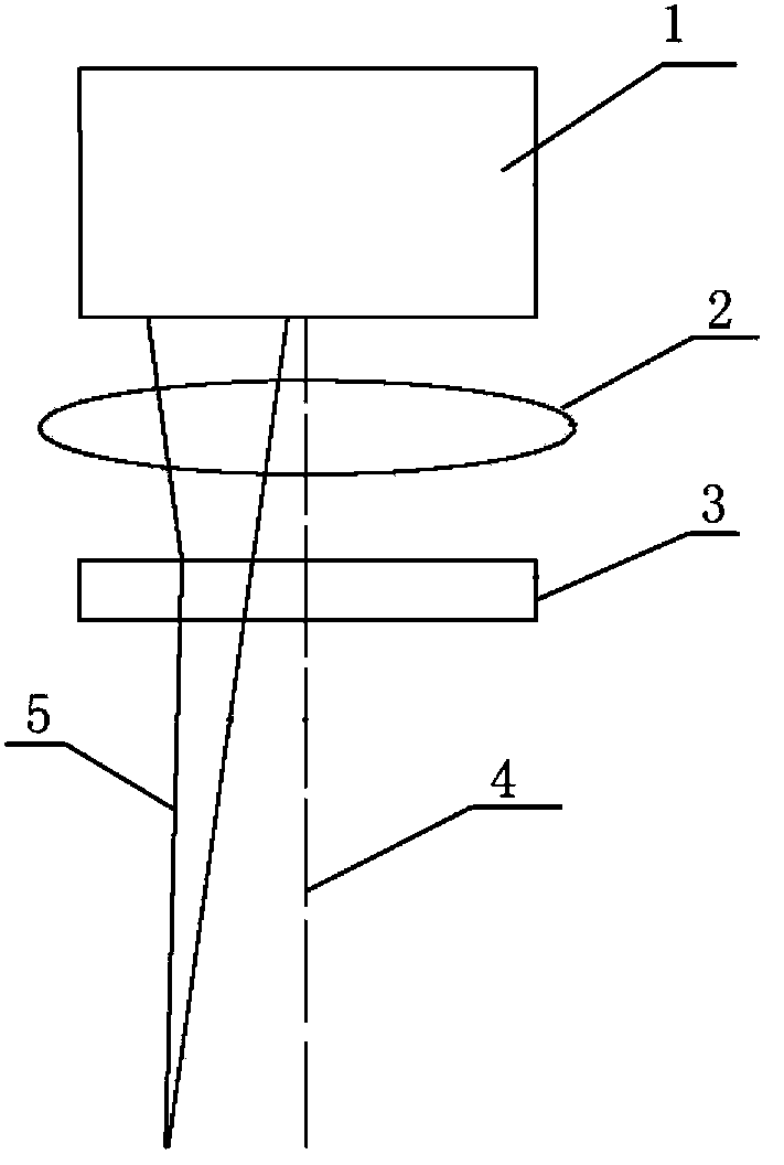
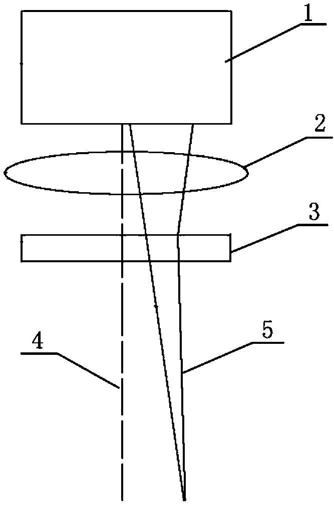
[0030] Please refer to figure 1 , figure 2 , is a schematic diagram of the structure of the ultrashort pulse laser processing small hole device of the present invention. like figure 1 , figure 2 As shown, the ultrashort pulse laser processing small hole device of the present invention, the ultrashort pulse laser processing small hole device includes a scanning galva...


PUM

PropertyMeasurementUnit
angleaaaaaaaaaa

Abstract

The invention provides a device for machining small holes by using ultrashort pulse laser and a small hole machining method. The device comprises a scanning galvanometer, a laser scanning focus lens and a wedge lens. The scanning galvanometer, the laser scanning focus lens and the wedge lens are arranged on the same central axis. A laser beam rotates around the central axis along a concentric circle track through the scanning galvanometer, is focused through the laser scanning focus lens and is deflected far away from the central axis through the wedge lens. The wedge lens and the laser beam rotate synchronously to keep the inclination angle of the laser beams to be the same. The device for machining small holes by using ultrashort pulse laser and the small hole machining method have the advantages that the small hole machining depth is increased and the machining quality and stability of the small holes are improved.

Description

technical field [0001] The invention relates to an ultrashort pulse laser processing small hole device and a small hole processing method. The processing device and method can improve the depth and quality of ultrashort pulse laser processing small holes, and are mainly used for processing air film holes of turbine blades of aeroengines. It belongs to the technical field of laser material processing. Background technique [0002] At present, the methods of using laser to process small holes mainly include fixed-point impact processing method, rotary cutting processing method and helical feed processing method. Generally speaking, the fixed-point impact method has high efficiency in machining small holes, and the aperture size is controlled by partial focus and energy, but the processing quality is the worst. However, the rotary cutting method has a large aperture range and a rounder aperture, but the processing efficiency is low. Low. The common disadvantage of the above t...

Claims


Application Information

Patent Timeline
Patent Type & Authority Applications(China)
IPC IPC(8): B23K26/36B23K26/04
Inventor 张晓兵孙瑞峰
Owner BEIJING AERONAUTICAL MFG TECH RES INST
Learn More