
Inductance value adjustable resonant antenna

A resonant antenna and inductance technology, applied in antennas, foldable/stretchable loop antennas, electrical components, etc., can solve the problem of changing inductance of high-frequency resonant antennas

Inactive Publication Date: 2013-12-04
GUIZHOU TAIGE TECH
View PDF5 Cites 5 Cited by
  • Summary
  • Abstract
  • Description
  • Claims
  • Application Information

AI Technical Summary

Problems solved by technology

[0011] The above methods are not suitable for changing the inductance of the high-frequency resonant antenna above 10MHz

Method used


Image

  • Inductance value adjustable resonant antenna

Examples


Embodiment 1

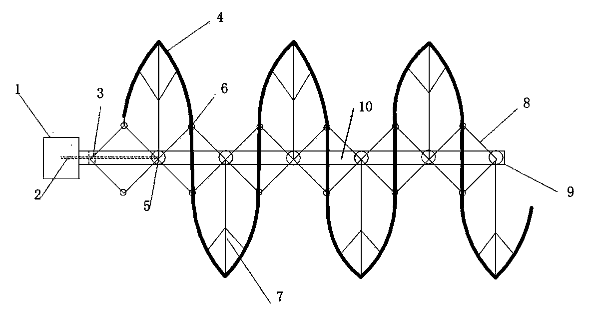
[0030] Such as figure 1 , a resonant antenna with adjustable inductance, which at least includes a voltage controller 1, a cylindrical inverse piezoelectric stretching effect material 2 made of barium calcium zirconate titanate material, a slide rail 9, a hinge bracket 8, an antenna bracket 7 and a resonance Coil 4. Among them, the voltage controller 1 adopts the da controller to control the XE-15S170 DC / DC module, and the voltage can vary from 15 to 170 volts, which controls the deformation of the inverse piezoelectric stretching effect material 2 within 5% of the length. The voltage controller 1 is arranged on one end of the aluminum slide rail 9, and the slide rail 9 is provided with a plastic hinge bracket 8. The hinge center node 5 is arranged in the chute 10 inside the slide rail 9 along the direction of the slide rail, and the hinge edge node 6 is between two adjacent hinge center nodes 5, and there is a connection between the hinge center node 5 and the hinge edge nod...

Embodiment 2

[0033] Compared with Example 1, the difference of Example 2 is that the drive components are (39~57 series) linear stepper motors and linear motor drive screw.

Embodiment 3

[0035] Compared with the embodiment 1, the difference of the embodiment 3 is that the driving mechanism of the central node of the push-pull hinge can also use thermostrictive material.


PUM


Abstract

The present invention relates to the radio equipment field, in particular to an inductance value adjustable resonant antenna. The inductance value adjustable resonant antenna comprises a voltage controller, an inverse piezoelectric telescopic effect material, a slide rail, a hinge support, an antenna support and a resonance coil. The inverse piezoelectric telescopic effect material pushes the hinge support to change the antenna gap of the resonant antenna to change the inductance value of the antenna, thereby fine tuning a resonant frequency. The inductance value adjustable resonant antenna enables the antenna gap to be changed equidistantly via a transmission hinge.

Description

technical field [0001] The invention relates to the field of radio equipment, in particular to a resonant antenna with adjustable inductance. Background technique [0002] An adjustable inductor is a commonly used inductive device. There are oscillating coils for semiconductor radios, horizontal oscillating coils for TV sets, horizontal linear coils, intermediate frequency notch coils, frequency compensation coils for audio, wave blocking coils, etc. [0003] There are usually two ways to change the size of the inductance at present. [0004] One: The method is to use threaded soft ferrite to change the position of the core in the coil; [0005] Two: Use a slide switch to change the number of turns of the coil, thereby changing the inductance of the inductor. [0006] The disadvantage of these two methods is that they have movable parts, which can only be adjusted manually and cannot be controlled automatically. [0007] In specific applications, the method of combining ...

Claims


Application Information

Patent Timeline
IPC IPC(8): H01Q1/36H01Q3/01H01Q7/02
Inventor 林宏肖健曹松
Owner GUIZHOU TAIGE TECH
Learn More