Automatic dehydration apparatus and method for waste oil

A dehydration device and gutter oil technology, applied in separation methods, chemical instruments and methods, dehydration/emulsification by mechanical methods, etc., can solve the problem that oil sludge and slag cannot be removed in time, increase the difficulty of oil-water separation, and thicken the oil-water interface and other problems, to achieve the effect of improving the oil-water separation effect, facilitating continuous and stable work, and good airtightness

Inactive Publication Date: 2015-03-04
JIANGSU UNIV
View PDF4 Cites 0 Cited by
  • Summary
  • Abstract
  • Description
  • Claims
  • Application Information

AI Technical Summary

Problems solved by technology

However, this oil-water separation device has the following disadvantages: first, the oily wastewater enters directly from the top of the device, and the strong impact force makes the emulsification of the oily wastewater serious, and also thickens the oil-water interface, thereby increasing the difficulty of subsequent oil-water separation ; Second, there is no slag removal facility at the bottom of the device, and the oil sludge and slag deposited in the oil tank for a long time cannot be removed in time, which affects the operation of the entire device; After half a year of use, there are too many oil layers, which increases the weight of the float, making it impossible to track and monitor, and the reliability of the operation is poor.

Method used


Image

  • Automatic dehydration apparatus and method for waste oil
  • Automatic dehydration apparatus and method for waste oil
  • Automatic dehydration apparatus and method for waste oil

Examples


Embodiment Construction

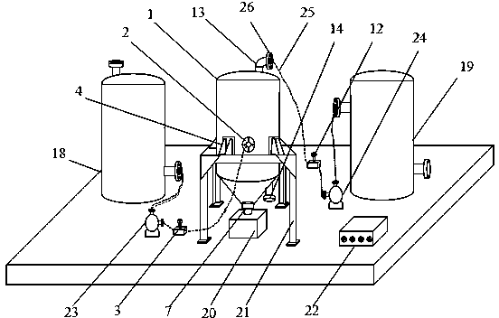
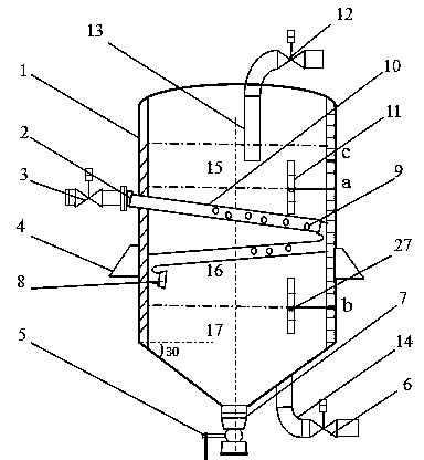
[0018] see figure 1 , the present invention includes dehydration tank 1, former waste oil storage tank 18, dehydration waste oil storage tank 19, sludge tank 20 these four tank bodies. Among them, the dehydration tank 1 is an integrated tank body formed by seamless welding of the tank roof, tank wall and tank bottom. The tank roof adopts a self-supporting ribbed spherical shell vault structure, which has good bearing capacity and light weight. . The top of the dehydration tank 1 is provided with an oil outlet, and one end of the dehydration oil suction pipe 13 extends into the inside of the dehydration tank 1 through the oil outlet on the top of the dehydration tank 1, and the other end of the dehydration oil suction pipe 13 stretches out of the dehydration tank 1 and One end of the oil delivery pipe 25 is connected by a flange 26, and the other end of the oil delivery pipe 25 is connected to the dewatered waste oil storage tank 19. A third electromagnetic valve 12 and a seco...


PUM


Abstract

The invention discloses an automatic dehydration apparatus and method for waste oil. According to the invention, a third solenoid valve and a second oil pump are arranged on an oil-conveying pipe located between a dehydration tank and a dehydrated waste oil storage tank, a first solenoid valve and a first oil pump are arranged on an oil-conveying pipe located between the dehydration tank and a raw waste oil storage tank, and the solenoid valves and the oil pumps are all connected with an embedded controller; when the first solenoid valve is opened and the first oil pump works, waste oil in the raw waste oil storage tank is injected into the dehydration tank, and the waste oil downwardly spirals to a throttle valve at a lower part along the inner surface of the wall of the raw waste oil storage tank through a bent oil pipe in an angle of 360 DEG, flows out through the throttle valve and is then injected into the dehydration tank at different angles through a plurality of through holes; after deposition of the raw waste oil in the dehydration tank for a period of time, an oil level detector is used to detect an interface. With the apparatus and method provided by the invention, a distance between an oil level and a water level is strictly controlled, an oil-water mixed layer maintains certain thickness all the time, artificial intervention is not needed, and automatic dehydration is realized.

Description

technical field [0001] The invention relates to waste oil treatment equipment, in particular to a waste oil automatic dehydration device and a control method. Background technique [0002] Waste oil and waste oil contain a lot of calorific value, which can generate a lot of heat as an alternative fuel. Converting waste grease and gutter oil into fuel can not only effectively save energy, but also effectively reduce environmental pollution. However, the water content of waste oil is high, as high as more than 40%, and it must be dehydrated before it can be used as an alternative fuel. At present, the dehydration of oil tanks is performed manually, and the separation of oil and water cannot be strictly controlled. The oil content in the drainage is relatively high, which not only causes waste of oil products, but also pollutes the environment. [0003] The Chinese patent application number is 03117169.9, and the patent literature titled "A Self-Control Float Valve Oil-Water ...

Claims


Application Information

Patent Timeline
Patent Type & Authority Patents(China)
IPC IPC(8): B01D17/025B01D17/12C10G33/06
Inventor 张荣标邱亮钱弼违
Owner JIANGSU UNIV
Why Eureka
Try Eureka