Micrometer-scale glucose sensor microelectrode

A glucose sensor and microelectrode technology, which is applied in sensors, medical science, diagnosis, etc., can solve the problems of changing the test environment, rejection, large volume, etc., and achieve the effect of reducing human body rejection and irritation

Active Publication Date: 2013-12-25
MEDTRUM TECH
View PDF8 Cites 25 Cited by
  • Summary
  • Abstract
  • Description
  • Claims
  • Application Information

AI Technical Summary

Problems solved by technology

Due to the relatively large size of the traditional size electrodes used in the past, they are more irritating to human tissues during implantation, resulting in more serious rejection reactions, changing the test environment, and thus affecting the detection results of the electrodes.

Method used


Image

  • Micrometer-scale glucose sensor microelectrode
  • Micrometer-scale glucose sensor microelectrode
  • Micrometer-scale glucose sensor microelectrode

Examples


Embodiment 1

[0080] double-sided microelectrode

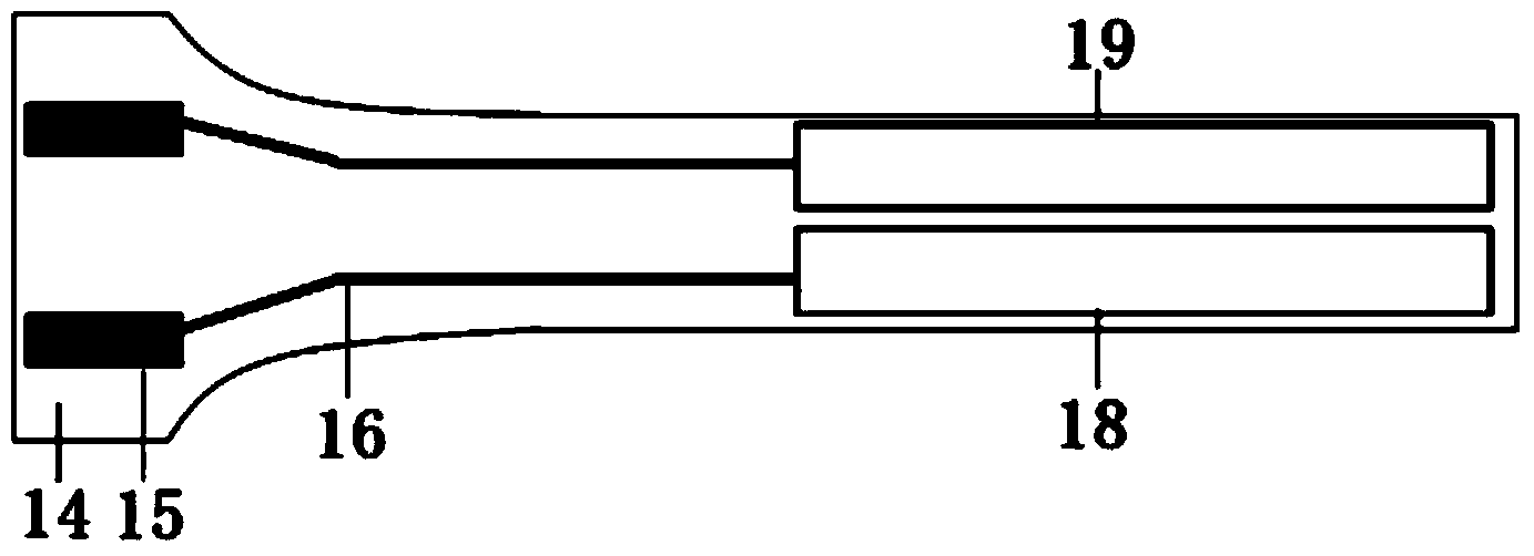
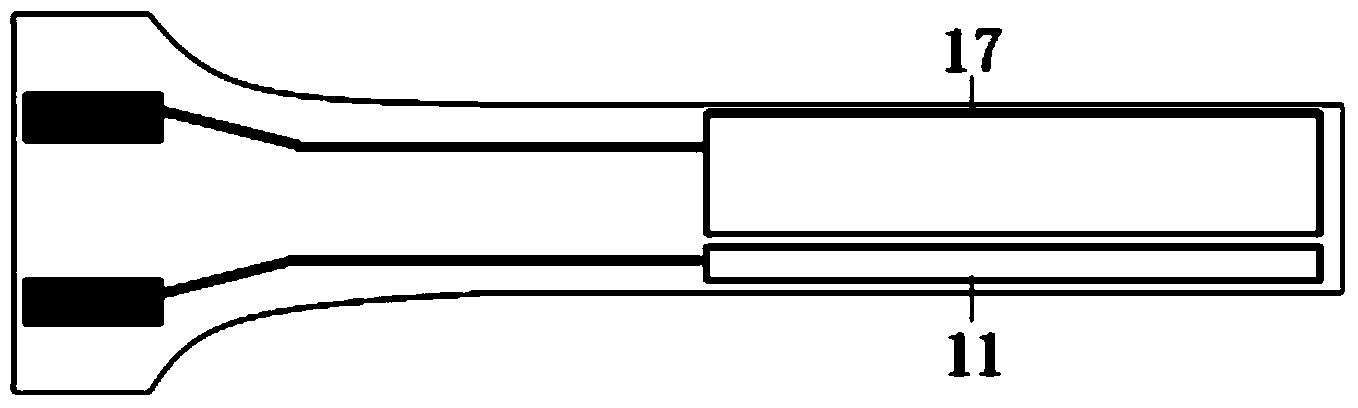
[0081] figure 1 and figure 2 For the double-sided microelectrode of the micrometer-scale glucose sensor microelectrode shown, the thickness of the substrate 14 is 0.01-0.8mm, each electrode is rectangular, the width of each electrode is 0.01-1mm, and the total length of the microelectrode is 0.5-8cm. The area is 0.1-2mm 2 , the counter electrode 17 and the reference electrode 11 are located on one surface of the substrate 14, the working electrode 18 and the auxiliary electrode 19 are located on the other surface of the substrate 14, and each electrode is connected to the gold PAD15 by a gold wire 16, and the PAD15 and each The electrodes are in one-to-one correspondence, the area of ​​the counter electrode 17 is three times that of the reference electrode 11, and the area of ​​the auxiliary electrode 19 and the working electrode 18 are equal.

Embodiment 2

[0083] multilayer microelectrode

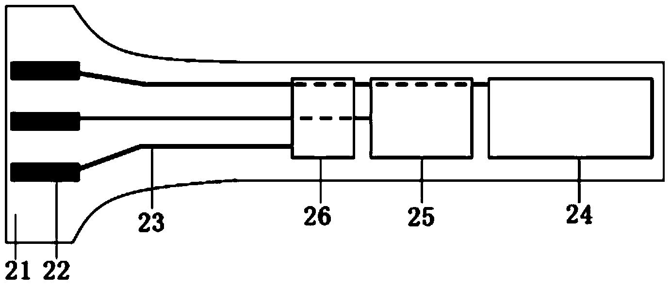
[0084] image 3 and Figure 4 In the multi-layer microelectrode of the micrometer-scale glucose sensor microelectrode shown, the substrate 21 is provided with a first insulating layer and a second insulating layer, and forms a ladder shape. The thicknesses of the substrate 21, the first insulating layer, and the second insulating layer are 0.01-0.8mm, each electrode is rectangular, the width of each electrode is 0.01-1mm, the total length of the microelectrode is 0.5-8cm, and the area of ​​each electrode is 0.1-2mm 2 , the counter electrode 24, the working electrode 25 and the reference electrode 26 are respectively arranged on the base 21, the first insulating layer, and the second insulating layer of the ladder structure, and each electrode is connected to the gold PAD22 by the gold wire 23, and the PAD22 and the Each electrode corresponds to one by one.

Embodiment 3

[0086] ring microelectrode

[0087] Figure 5 The ring-shaped microelectrode of the micrometer-scale glucose sensor microelectrode shown, the front part of the base 27 is cylindrical, with a diameter of 0.1-1mm, the total length of the microelectrode is 0.5-8cm, and the area of ​​each electrode is 0.1-10mm 2 , the counter electrode 30, the working electrode 31 and the reference electrode 32 are annularly distributed on the substrate 27, and each electrode is connected to the gold PAD28 through the gold wire 29 passing through the interior of the insulating substrate, and the PAD28 corresponds to each electrode one by one.


PUM


Abstract

The invention relates to the field of detecting instruments, in particular to a micrometer-scale glucose sensor microelectrode. The micrometer-scale glucose sensor microelectrode comprises a substrate, a working electrode and a counter electrode, the front portion of the substrate is a working area, the working electrode and the counter electrode are located in the working area, the maximum diameter of the cross section of the working area is less than or equal to 1 millimeter, PADs in one-to-one correspondence to the electrodes are arranged at the tail of the substrate, and each of the working electrode and the counter electrode is connected with the corresponding PAD through a lead. The electrodes are reasonably distributed on the planar or columnar insulating substrate and width of each electrode or cross-sectional diameter of each columnar electrode is limited to effectively reduce size of the electrode, so that rejection reaction of receptors is reduced.

Description

technical field [0001] The invention relates to the field of detection instruments, in particular to a microelectrode for a micron-scale glucose sensor. Background technique [0002] The first type of traditional blood glucose monitor is an invasive measuring instrument, the method is fingertip blood measurement test; Type blood glucose monitor, usually this type of blood glucose meter is implanted into the subcutaneous tissue by adding a glucose sensor to the front end of the fine needle, and using the contained glucose oxidase to measure the consumption of oxygen or the concentration of hydroxide ions in the interstitial fluid of the subcutaneous tissue produced, thereby converting to glucose values. [0003] In the continuous blood glucose measurement system, the glucose sensor is crucial. Studies have shown that it is feasible to continuously detect glucose in the body through an implantable glucose sensor. Considering the convenience, safety and reliability of the use,...

Claims


Application Information

Patent Timeline
Patent Type & Authority Applications(China)
IPC IPC(8): A61B5/1486
Inventor 不公告发明人
Owner MEDTRUM TECH
Why Eureka
Try Eureka