Continuous-casting and continuous-rolling integrating device and process

An integrated technology of continuous casting and rolling, applied in the direction of metal rolling, temperature control, etc., can solve the problems of inability to improve production efficiency, potential safety hazards, uncontrollable billet temperature, etc., to improve equipment utilization and production efficiency, The effect of improving production automation and improving metal yield

Active Publication Date: 2013-12-25
HUBEI CENT STEEL UNION METALLURGICAL ENG
View PDF5 Cites 30 Cited by
  • Summary
  • Abstract
  • Description
  • Claims
  • Application Information

AI Technical Summary

Problems solved by technology

Both of the above two processes have the following disadvantages: 1. The heating gas is a combustible gas, which has potential safety hazards
2. The heating furnace needs to be preheated, and the energy consumption is high
3. Combustion produces a large amount of carbon dioxide, which is not conducive to environmental protection
4. The billet heating time is long and the heating efficiency is low
5. The slab oxidation rate is high, and the slab metal yield is low
6. In case of failure, production must be stopped for maintenance, and maintenance is difficult
7. The gas generator and heating furnace are large in size, occupy a large area, and require high investment
The invention has the following problems: the slab is cut and directly enters the heating furnace, which cannot be solved when there are failures such as continuous cutting of the slab during production; the traverse device is a single-flow conveying roller table, and the slab feeding speed is slow, which greatly restricts production efficiency
The slab that needs to be cooled off-line must be heated by the heating furnace before it can be off-line, which greatly increases energy consumption; there are too many equipments between the heating furnace and the rolling mill, the distance is too long and there is no i

Method used


Image

  • Continuous-casting and continuous-rolling integrating device and process
  • Continuous-casting and continuous-rolling integrating device and process
  • Continuous-casting and continuous-rolling integrating device and process

Examples


Example Embodiment

[0022] Below in conjunction with accompanying drawing and embodiment, the present invention will be further described:
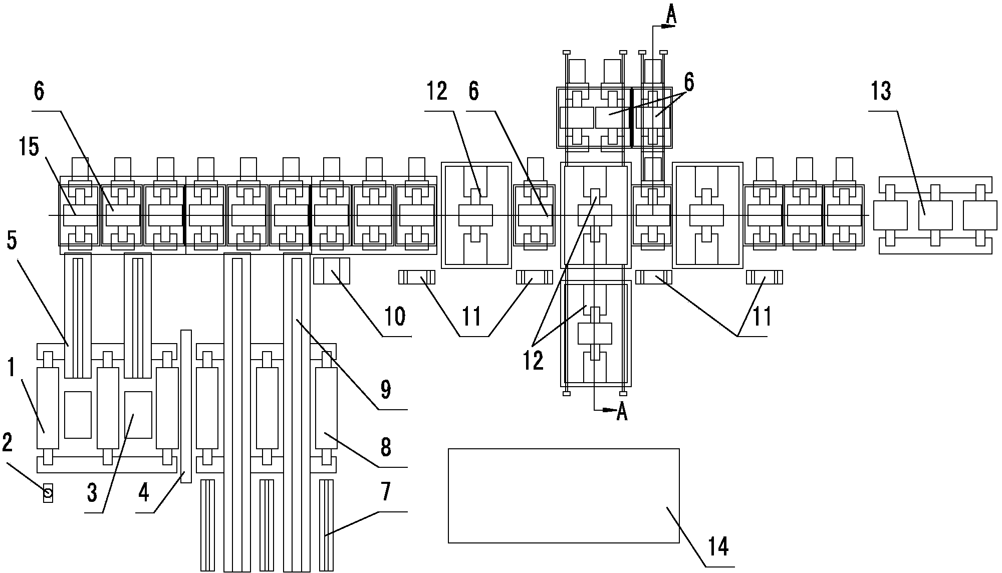
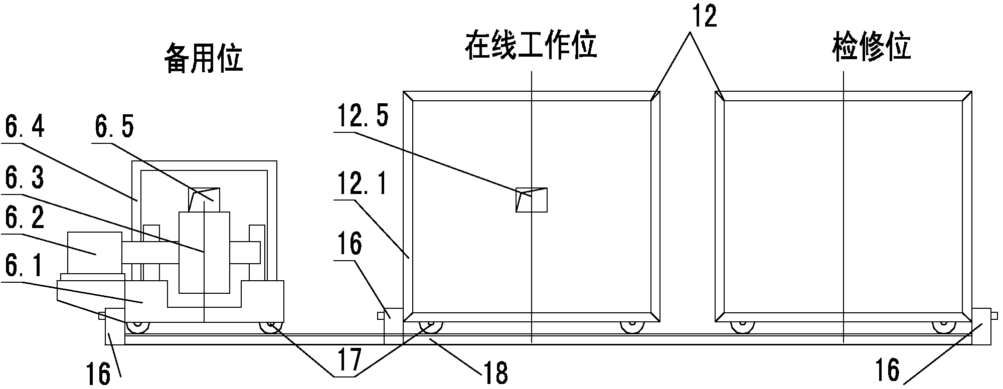
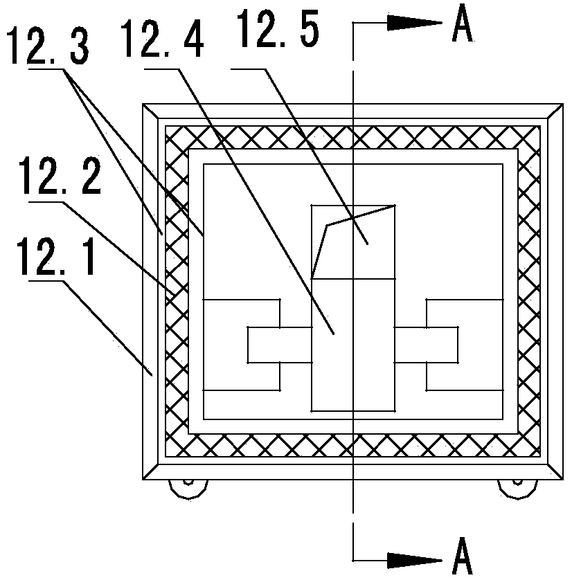
[0023] like Figure 1-4 As shown in the figure, an integrated continuous casting and rolling device implemented according to the present invention mainly includes a blank discharge roller table 1, and is characterized in that: an online weighing device 3 and a fixed-length detection device 2 are provided in the blank discharge area of ​​the blank discharge roller table 1 , The blanking roller table 1 and the transition roller table 8 are continuously connected in a straight line, and a movable baffle 4 that can be automatically raised and lowered is arranged at the butt; The roller table 6 is connected to the billet splitting device 5 with a heat preservation device, and the billet can be moved from the billet rolling table 1 to the hot delivery roll table 6 through the billet splitting device 5; the transition roll table 8 (the billet roll 1) A transitiona...


PUM


Abstract

The invention relates to a continuous-casting and continuous-rolling integrating device and a continuous-casting and continuous-rolling integrating process. An ejection roller way in an ejection roller way ejection area and a transition roller way are linearly and continuously jointed and a moveable baffle plate which can automatically lift is arranged at the joint; the ejection roller way and a heat conveying roller way are jointed through a casting blank separating device with a heat-preserving device; a set of blank-separating collecting device which can move bi-directionally is jointly used between a cooling bed and the transition roller way as well as between the transition roller way and the heat conveying roller way and can drive casting blanks to bi-directionally move between the cooling bed and the transition roller way; a heater is arranged on the heat conveying roller way; the tail end of the heat conveying roller way is jointed with a rolling machine. According to heat conveying and rolling requirements, the casting blanks are selected, separated and collected, according to casting blank temperature data which is detected in real time, the heating temperature and the heating time are automatically adjusted, the casting blanks are heated to the temperature meeting the rolling requirement and are fed into the rolling machine to be rolled, the metal yield can be increased, the continuous-casting blank quality can be improved, the energy consumption can be reduced, the utilization efficiency, the maintenance rate and the production efficiency of equipment are improved, and the investment cost and the operation cost are reduced.

Description

technical field [0001] The invention belongs to a new continuous casting and rolling integrated device and process, and mainly relates to the continuous casting and rolling process and related supporting equipment. Background technique [0002] There are two traditional continuous casting and rolling processes. One is that the slab is directly cooled off the line, and when production needs, the slab is sent to a gas heating furnace for heating and then rolled; the other is that the hot slab is directly sent to the heating furnace through the roller table, and then rolled. The above two processes all have the following disadvantages: 1. The heating gas is a combustible gas, which has potential safety hazards. 2. The heating furnace needs to be preheated, and the energy consumption is high. 3. Combustion produces a large amount of carbon dioxide, which is not conducive to environmental protection. 4. The billet heating time is long and the heating efficiency is low. 5. The...

Claims


Application Information

Patent Timeline
IPC IPC(8): B21B1/46B21B37/74
Inventor 符乃良寿昱斐
Owner HUBEI CENT STEEL UNION METALLURGICAL ENG
Why Eureka
Try Eureka