Dual-frequency receiving antenna and dual-frequency rectifying antenna

A technology for receiving antennas and rectennas, applied to antennas, slot antennas, resonant antennas, etc., can solve the problems of small gain, poor reliability of rectifier circuits, large size of dual-frequency rectennas, etc., and achieve the effect of increasing gain and improving matching

Inactive Publication Date: 2013-12-25
UNIV OF ELECTRONICS SCI & TECH OF CHINA
View PDF6 Cites 21 Cited by
  • Summary
  • Abstract
  • Description
  • Claims
  • Application Information

AI Technical Summary

Problems solved by technology

[0017] The present invention solves the problem that the existing dual-frequency receiving antenna has a large size and small gain; the dual-frequency rectifying antenna has a large size, cannot receive weak energy, is not suitable for long-distance transmission, and has poor reliability of the rectifying circuit in the rectifying antenna , while providing a dual-frequency receiving antenna and a dual-frequency rectenna

Method used


Image

  • Dual-frequency receiving antenna and dual-frequency rectifying antenna
  • Dual-frequency receiving antenna and dual-frequency rectifying antenna
  • Dual-frequency receiving antenna and dual-frequency rectifying antenna

Examples


Embodiment 1

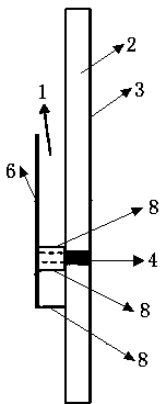
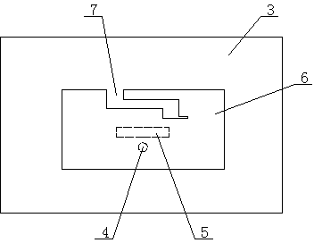
[0059] The dual-frequency receiving antenna of this embodiment includes a rectangular radiation patch, and the radiation patch is provided with a Z-shaped slot for realizing dual-frequency characteristics, and the lower end of the radiation patch is sequentially connected with a FR4 dielectric substrate layer and a coaxial line. A metal grounding plate, the coaxial line is connected to the back-end circuit, an air dielectric layer is formed between the radiation patch and the FR4 dielectric substrate layer, and the coaxial line between the radiation patch and the FR4 dielectric substrate layer There are metal sheets symmetrically arranged on the left and right, the upper end of the metal sheet is connected to the radiation patch, and the lower end is connected to the FR4 dielectric substrate layer; one end surface of the radiation patch is also connected to a metal sheet connected to the FR4 dielectric substrate layer.

[0060] In this embodiment, the length of the rectangular ...

Embodiment 2

[0065] The dual-frequency receiving antenna of this embodiment includes a rectangular radiation patch, and the radiation patch is provided with a Z-shaped slot for realizing dual-frequency characteristics, and the lower end of the radiation patch is sequentially connected to Arlon 25N (Arlon 25N , polytetrafluoroethylene) dielectric substrate layer and metal grounding plate, the coaxial line is connected to the back-end circuit, an air dielectric layer is formed between the radiation patch and the Arlon 25N dielectric substrate layer, and the radiation patch and the Arlon 25N dielectric substrate layer are formed. The coaxial line between the Arlon 25N dielectric substrate layers is symmetrically arranged with metal sheets, the upper end of the metal sheet is connected to the radiation patch, and the lower end is connected to the Arlon 25N dielectric substrate layer; one end surface of the radiation patch Also attached is a metal sheet connected to the Arlon 25N dielectric subs...

Embodiment 3

[0072] The dual-frequency rectifying antenna of this embodiment includes the above-mentioned dual-frequency receiving antenna (embodiment 1 or embodiment 2), and the dual-frequency receiving antenna is sequentially connected in series with an input filter structure, a rectifier circuit and an output filter via its coaxial line. structure, the input filter structure, the rectifier circuit and the output filter structure are connected with a matching circuit.

[0073] Further, the rectifier circuit is a voltage doubling topology, and the voltage doubling topology includes a radio frequency input terminal and a load DC output terminal, the radio frequency input terminal is connected to the load DC output terminal, and the radio frequency input terminal is connected to the load DC output terminal There are also three branches connected between the ends, the first branch is connected in series with a capacitor and a diode, the cathode of the diode is connected to the capacitor, and ...


PUM


Abstract

The invention discloses a dual-frequency receiving antenna and a dual-frequency rectifying antenna. The dual-frequency receiving antenna and the dual-frequency rectifying antenna are used for solving the problems that an existing dual-frequency receiving antenna is large in size and small in gain, an existing dual-frequency rectifying antenna is large in size, can not receive weak energy and is not suitable for remote transmission, and a rectifying circuit is poor in reliability. The dual-frequency receiving antenna comprises a rectangular radiating patch. A Z-type groove used for achieving dual-frequency characteristics is formed in the radiation patch. The lower end of the radiation patch is sequentially connected with a dielectric substrate layer and a metal earth plate through a coaxial line. The coaxial line is in circuit connection with the rear end of the radiation patch. An air dielectric layer is formed between the radiation patch and the dielectric substrate layer. The portions, arranged between the radiation patch and the dielectric substrate layer, outside the coaxial line are provided with metal sheets in a bilaterally-symmetric mode. The upper ends of the metal sheets are connected with the radiation patch. The lower ends of the metal sheets are connected with the dielectric substrate layer. One end face of the radiation patch is further connected with the metal sheets connected with the dielectric substrate layer. The dual-frequency receiving antenna and the dual-frequency rectifying antenna can be widely applied in the fields of communication, medical treatment, industry and the like, for microwave power transmission.

Description

technical field [0001] The invention belongs to the antenna technology in the field of wireless energy transmission, and in particular relates to a dual-frequency receiving antenna and a dual-frequency rectifying antenna. Background technique [0002] Wireless power transmission, that is, the technology of transferring energy without passing through power lines, can free people from the constraints of wires. Wireless charging transmission methods can generally be divided into three types: electromagnetic induction type, magnetic field resonance type, and radio wave radiation type. Among them, the radio wave radiation type is also called microwave power transmission (MPT), that is, the electric energy is converted into microwaves for radiation transmission and power supply, which is suitable for long-distance transmission. In 1899, the advent of "Tesla Coil" planted the seeds for the development of MPT. The modern MPT experiment was completed in 1964, using microwaves t...

Claims


Application Information

Patent Timeline
Patent Type & Authority Applications(China)
IPC IPC(8): H01Q9/04H01Q13/10H01Q5/01H01Q1/48H01Q5/10
Inventor 杨雪松卢萍王秉中
Owner UNIV OF ELECTRONICS SCI & TECH OF CHINA
Why Eureka
Try Eureka