Signal source circuit

A signal source and circuit technology, applied in electrical components and other directions, can solve the problems of inconvenient low-power system application, high power consumption, complex circuits, etc., and achieve the effects of less clutter, stable signal output, and simple circuit structure.

Inactive Publication Date: 2013-12-25
KUNSHAN XINJINFU PRECISION ELECTRONICS
View PDF3 Cites 0 Cited by
  • Summary
  • Abstract
  • Description
  • Claims
  • Application Information

AI Technical Summary

Problems solved by technology

However, its circuit is complex and consumes a lot of power

Method used


Image

  • Signal source circuit

Examples


Embodiment Construction

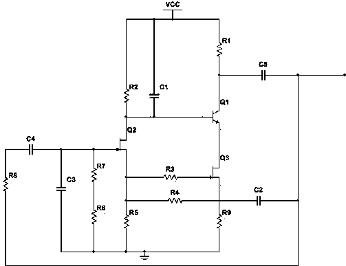
[0012] like figure 1 As shown, the circuit triode, field effect transistor, resistor and capacitor of the present invention, the base of the first triode Q1 is connected with the drain of the first field effect transistor Q2, and the drain of the first field effect transistor Q2 passes through the second resistor R2 is connected to a positive voltage, the collector of the first transistor Q1 is connected to a positive voltage through the first resistor R1, the emitter of the first transistor Q1 is connected to the drain of the second field effect Q3, and the second field effect Q3 The gate of the first field effect transistor Q2 is grounded through the series connection of the third resistor R3 and the fifth resistor R5, the source of the first field effect transistor Q2 is grounded through the fifth resistor R5, and the gate of the first field effect transistor Q2 is connected through the seventh resistor R7 and the sixth resistor R7. The series connection of resistor R6 is g...


PUM


Abstract

The invention discloses a signal source circuit which comprises a triode, a field-effect tube, a resistor and a capacitor. The signal source circuit is simple in structure, signals are output stably, the number of clutter is small, and noise is low. The signal source circuit is suitable for being used in a low-power electronic system.

Description

[0001] technical field [0002] The invention relates to a signal source circuit, in particular to a sine wave signal source circuit. Background technique [0003] The signal source circuit is the core unit circuit of an analog integrated circuit, especially in power management chips, the signal source often determines the performance indicators of such chips, and it is widely used in various analog circuits such as oscillators, phase-locked loops, and data converters. and digital-analog hybrid integrated circuits. However, its circuit is complex and consumes a lot of power, which is not convenient for low-power system applications. [0004] Therefore need a kind of new technical scheme to solve the above problems. Contents of the invention [0005] Purpose of the invention: In view of the problems and deficiencies in the above-mentioned prior art, the purpose of the invention is to provide a signal source circuit with stable signal generation and low noise. [0006] Te...

Claims


Application Information

Patent Timeline
IPC IPC(8): H03B28/00
Inventor 王火明
Owner KUNSHAN XINJINFU PRECISION ELECTRONICS
Why Eureka
Try Eureka