Application of trimethylene sulfide serving as hydrate accelerant

A technology of hydrate accelerator and trimethethylenesulfur, which is applied in the direction of sulfur compounds, carbon compounds, hydrocarbons, etc., can solve the problems of slow reaction rate, difficult treatment of waste liquid, and harsh conditions for hydrate formation, so as to improve hydration The formation temperature of gas hydrates and the effect of promoting the formation of gas hydrates

Active Publication Date: 2015-05-20
GUANGZHOU INST OF ENERGY CONVERSION - CHINESE ACAD OF SCI
View PDF0 Cites 0 Cited by
  • Summary
  • Abstract
  • Description
  • Claims
  • Application Information

AI Technical Summary

Problems solved by technology

[0003] The purpose of the present invention is to provide the application of sulfur trimethylene as a hydrate accelerator. As a hydrate accelerator that is easy to recycle and has a good promoting effect, trimethylene sulfur solves the problems existing in the application process of the current gas hydrate method. The conditions for hydrate formation are harsh, the reaction rate is slow, and the waste liquid is difficult to deal with, etc.

Method used


Image

  • Application of trimethylene sulfide serving as hydrate accelerant

Examples


Embodiment 1

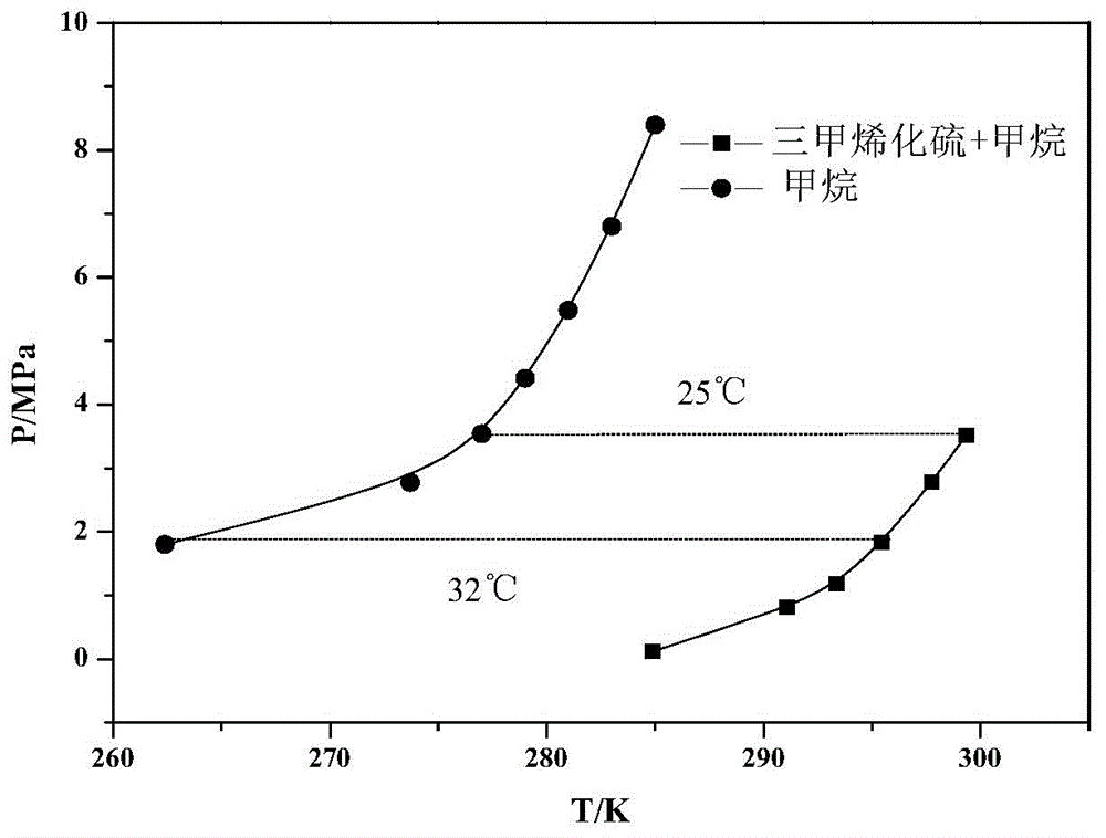
[0016] Vacuum the inside of the reactor, inject 20ml of trimethethylenesulfur and 135mL of deionized water into the reactor (about 1 / 2 of the viewing window), feed methane gas up to 0.01-5.0MPa, turn on the reactor and stir at 600-800rpm, Turn on the refrigeration cycle, cool down the system and observe until hydrate solids are formed in the reactor. The temperature of the system is gradually raised at a rate of 0.1K each time until there is a trace of hydrate in the reactor. Record the temperature and pressure at this time as the equilibrium temperature and pressure of the hydrate formation phase. When the temperature is 285.90, 291.10, 293.35, 295.45, 297.76, 299.35K, the phase equilibrium pressures are 0.12, 0.81, 1.18, 1.83, 2.78, 3.52MPa respectively. In the same way, the determination of CH 4 The phase equilibrium condition of hydrate is that when the temperature is 275.00, 277.00, 279.00, 281.00, 283.00, 285.00K, its equilibrium pressure is 2.82, 3.54, 4.41, 5.48, 6.8...

Embodiment 2

[0018] Inject trimethethylenesulfur / water with a volume fraction of 7.4% into the reactor, and feed the coal bed gas (CH 4 (0.25) / N 2 (0.70) / O 2 hydrate, CH 4 than N 2 , O 2 It is easy to form hydrates, so as to achieve the enrichment of CH in the hydrate phase 4 the goal of. Decomposition of the hydrate phase yields concentrated CH 4 Mixed gas, and then continue to pass the mixed gas into the reactor, and circulate the previous generation step for secondary enrichment and third enrichment, decompose the hydrate phase, and obtain CH 4 The concentration is as high as 72%.

Embodiment 3

[0020] Inject trimethethylenesulfur / water with a volume fraction of 10% into the reactor, and introduce 17.0% CO 2 flue gas (CO 2 (0.17) / N 2 (0.8215) / SO 2 (0.085)) or IGCC synthesis gas (H 2 (0.61) / CO 2 (0.39)), gas separation is carried out at 5-30°C and 0.01-5MPa. easily hydrated CO 2 into the hydrate phase, thereby forming a CO-rich 2 The gas hydrate slurry phase and N-rich 2 or H 2 the residual gaseous phase. The high concentration of N 2 or H 2 It is extracted under constant pressure as a separated product. will be rich in CO 2 The hydrate slurry phase is pumped into the hydrate decomposition tank for decomposition to obtain a high concentration of CO 2 mixed gas. Then the mixed gas continues to be passed into the reactor, and the previous generation step is circulated to carry out secondary enrichment and third enrichment, decompose the hydrate phase, and the obtained CO 2 The concentration is as high as 98%.


PUM


Abstract

The invention discloses the application of trimethylene sulfide serving as a hydrate accelerant. Serving as the hydrate accelerant being insoluble in water and high in boiling point, the trimethylene sulfide greatly lowers hydrate generation conditions, raises hydrate forming temperature, can raise gas hydrate generating temperature by 25-32DEG C under the same pressure and greatly improves gas hydrate generation, wherein the gas hydrate generation ratio ranges from 0.1mol*min<-1>*m<-3> to 0.5mol*min<-1>*m<-3>. Serving as the hydrate accelerant, the trimethylene sulfide can be recycled.

Description

Technical field: [0001] The invention relates to the technical field of gas hydrate formation and application, in particular to the application of sulfur trimethylene as a hydrate accelerator. Background technique: [0002] Gas hydrate (hereinafter referred to as hydrate) is a gas composed of small molecules (such as CH 4 、C 2 h 6 , CO 2 etc.) and the main body of water molecules in the low temperature, high pressure environment to form a non-stoichiometric crystalline cage compound. In hydrates, the main water molecules are connected in space through hydrogen bonds to form a series of polyhedral cavities. When these cavities are filled with gas molecules, they are thermodynamically stable, and the thermal energy corresponding to latent heat is accumulated and stored in the formed cages. in the crystals of hydrates. Due to the unique physical and chemical properties of gas hydrate, it has been proposed to apply the hydrate method to gas storage and transportation, sewag...

Claims


Application Information

Patent Timeline
Patent Type & Authority Patents(China)
IPC IPC(8): C01B3/50C01B3/02C01B31/20C01B21/04B01D53/00C10L3/10C07C7/00C07C11/04C07C9/04C07C9/06C07C9/08C01B17/56C01B32/50
CPCY02P20/50
Inventor 李小森吕秋楠陈朝阳冯景春李刚
Owner GUANGZHOU INST OF ENERGY CONVERSION - CHINESE ACAD OF SCI
Why Eureka
Try Eureka