
Thermoacoustic driven stirling engine

A Stirling engine and thermoacoustic technology, applied in the field of engines and Stirling engines, can solve problems such as reducing engine reliability and shortening engine service life, and achieve the effects of reducing failure sources, high conversion efficiency and simple structure

Inactive Publication Date: 2014-01-01
冯智勇
View PDF9 Cites 2 Cited by
  • Summary
  • Abstract
  • Description
  • Claims
  • Application Information

AI Technical Summary

Problems solved by technology

[0004] The disadvantage of the Stirling engine is: the traditional Stirling engine usually has moving parts that are easy to wear such as a valve piston or a displacer, which consumes energy and increases a potential source of failure during the movement, thereby , reducing the reliability of the engine and shortening the service life of the engine

Method used


Image

  • Thermoacoustic driven stirling engine

Examples


Embodiment Construction

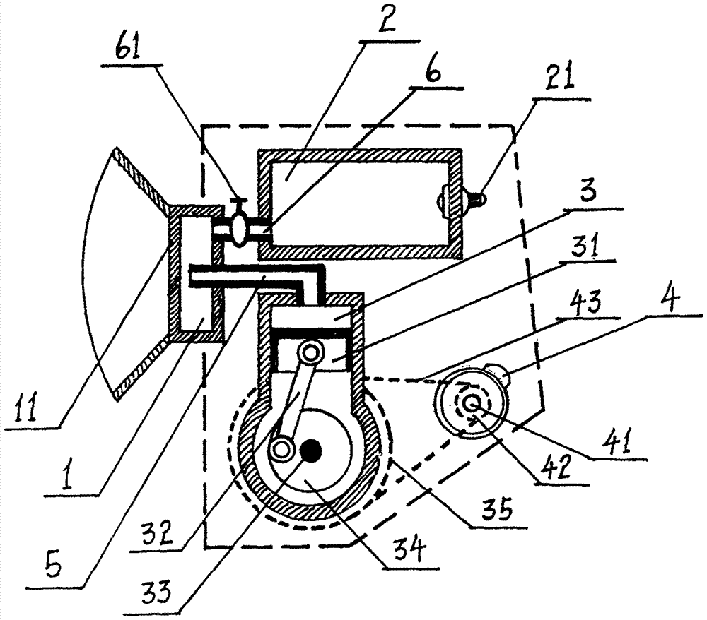
[0015] figure 1 The shown "a thermoacoustic-driven Stirling engine" is composed of four core components: a heat chamber 1, a high-pressure gas storage cylinder 2, a power cylinder 3, and a motor 4 (a motor integrating electric and power generation functions). , the power cylinder 3 is communicated with the heat chamber 1 by setting the air passage 5, and the heat chamber 1 is communicated with the high-pressure gas cylinder 2 by setting an upper air passage 6, and the middle part of the upper air passage 6 is provided with an air valve 61. Except for the motor 4, the whole structure of the above components is fully enclosed and isolated from the outside world, and its interior is filled with high-pressure working gas, which is helium.

[0016] Described power cylinder 3 is made up of its internal power piston 31, connecting rod 32, flywheel 34 and the engine shaft 33 supporting take-off wheel 34, and the other end of engine shaft 33 is also provided with large belt pulley 35. ...


PUM


Abstract

The invention discloses a thermoacoustic driven stirling engine and belongs to the field of applications of thermomotors. The thermoacoustic driven stirling engine is formed by four core components namely a high pressure air storage bottle, a hot chamber, a power air cylinder and a motor; the power air cylinder is communicated with the hot chamber by arranging an air descending channel; the hot chamber is communicated with the high pressure air storage bottle by arranging an air ascending channel; an air valve is arranged in the middle of the air ascending channel; an integral structure which is formed by the high pressure air storage bottle, the hot chamber and the power air cylinder except the motor is total sealing; the interior of the integral structure is filled with high-pressure working medium gas which can be hydrogen, helium, nitrogen or air and the like. Compared with the traditional stirling engine, the thermoacoustic driven stirling engine does not adopt easy-to-wear moving components such as a distribution piston or an air remover, but moves the air through cold and hot space which is formed by the high pressure air storage bottle and the hot chamber, so that the reliability of the engine is greatly improved. The thermoacoustic driven stirling engine can be applied to a temperature difference and waste heat power generation system and a solar photo-thermal power generation system.

Description

technical field [0001] The invention relates to an engine that can be applied to thermal power generation and solar thermal power generation CSP technology, in particular to a thermoacoustic driven Stirling engine, which belongs to the field of heat engine utilization. Background technique [0002] The Stirling engine was invented in 1816 by Robert Stirling, a pastor in London, so it was named "Stirling engine". The Stirling engine is an external combustion heat engine with a closed working medium gas inside (hydrogen, nitrogen, helium or air can be used as the working medium), and it works according to the Stirling cycle. Its theoretical efficiency is almost equal to the theoretical maximum efficiency, which is called the Carnot cycle efficiency. [0003] The advantage of the Stirling engine is that it does not have the problem of detonation work of the traditional internal combustion engine. It is an engine with high efficiency, low noise, low pollution and low operating ...

Claims


Application Information

Patent Timeline
Patent Type & Authority Applications(China)
IPC IPC(8): F02G1/043
Inventor 冯智勇
Owner 冯智勇
Learn More