Energy-saving type catalytic bed system with controllable temperature

A catalytic bed, energy-saving technology, applied in the field of catalytic bed, can solve the problems of poor energy saving effect, low heat recovery efficiency, large heat loss of catalytic combustion bed furnace structure, etc., and achieve the effect of uniform reflux and uniform combustion

Inactive Publication Date: 2015-07-22
赛智环保科技(天津)有限公司
View PDF5 Cites 0 Cited by
  • Summary
  • Abstract
  • Description
  • Claims
  • Application Information

AI Technical Summary

Problems solved by technology

[0002] At present, the catalytic bed is the most used in the treatment of industrial volatile organic pollutants. The catalytic bed is usually made of heat-resistant steel plates or industrial furnace masonry materials. The air inlet and outlet of the existing catalytic combustion bed structure Located at the upper and lower ends of the catalytic combustion bed, although the existing structure can realize catalytic combustion, there are the following problems: 1. The structure of the catalytic combustion bed furnace itself has a large heat loss, and the heat recovery and utilization efficiency is low; 2. The catalytic combustion bed furnace The temperature in the body structure is uneven, and the overall temperature is high in the center and low in the edge, which reduces the combustion efficiency of industrial volatile organic pollutants and affects the purification rate of catalytic combustion. 3. The energy saving effect is poor and does not meet the requirements of energy saving and emission reduction

Method used


Image

  • Energy-saving type catalytic bed system with controllable temperature
  • Energy-saving type catalytic bed system with controllable temperature
  • Energy-saving type catalytic bed system with controllable temperature

Examples


Embodiment Construction

[0037] The present invention will be further described in detail below through the specific examples, the following examples are only descriptive, not restrictive, and cannot limit the protection scope of the present invention with this.

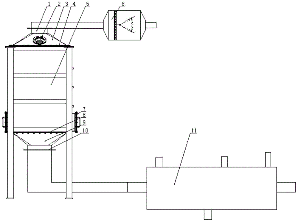
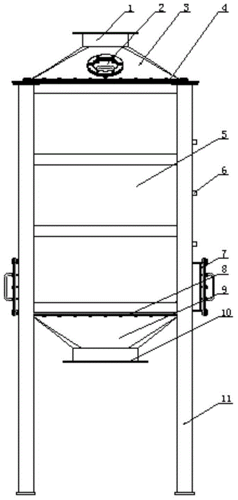
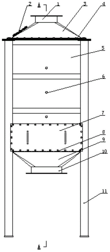
[0038] A temperature-controllable energy-saving catalytic bed system, including an inlet heater 6, a catalytic bed and a heat exchanger 11, the catalytic bed includes an inlet cover 3, a furnace body 5, and an air outlet cover 9, and the upper end of the furnace body is fixed with an air intake Hood, the lower end of the furnace body is fixed with the gas outlet hood, the inlet heater is connected to the inlet hood through a pipe, the gas inlet 1 and the explosion-proof pressure relief port 2 are set at the upper end of the gas inlet hood, and the gas outlet 10 is set at the lower end of the gas outlet hood, and the furnace body includes the periphery of the furnace body Plate 22 and its upper end plate 4 fixed at its upper end and its lower ...


PUM


Abstract

The invention relates to an energy-saving type catalytic bed system with the controllable temperature. The energy-saving type catalytic system comprises a gas inlet heater, a catalytic bed and a heat exchanger. A gas inlet channel and a gas outlet channel are alternately formed between a furnace body inner surrounding plate and a furnace body outer surrounding plate. The inlet of the gas inlet channel is formed in an upper end plate, and the outlet of the gas inlet channel is formed between a lower end plate and the furnace body inner surrounding plate. The inlet of the gas outlet channel is formed between the upper end plate and the furnace body inner surrounding plate, and the outlet of the gas outlet channel is formed in the lower end plate. The heater is arranged in a furnace body corresponding to the outlet of the gas inlet channel. A gas outlet flow guide cover is arranged on the lower face of the middle of the lower end plate corresponding to the outlet of a gas outlet cover. A catalytic tail gas inlet, a catalytic tail gas outlet, a catalytic gas inlet, a catalytic gas outlet, a desorption gas supply inlet and a desorption gas supply outlet are formed in the heat exchanger. By the adoption of the energy-saving type catalytic bed system, heat efficiency of the catalytic bed is effectively improved, the heat loss is reduced, the heat recovery utilization rate, combustion efficiency and the purification rate are improved, heat exchange is increased, heat energy is more reasonably utilized, and the energy saving and emission reduction requirements are met.

Description

technical field [0001] The invention belongs to the field of catalytic beds, in particular to a temperature-controllable energy-saving catalytic bed system. Background technique [0002] At present, the catalytic bed is the most used in the treatment of industrial volatile organic pollutants. The catalytic bed is usually made of heat-resistant steel plates or industrial furnace masonry materials. The air inlet and outlet of the existing catalytic combustion bed structure Located at the upper and lower ends of the catalytic combustion bed, although the existing structure can realize catalytic combustion, there are the following problems: 1. The structure of the catalytic combustion bed furnace itself has a large heat loss, and the heat recovery and utilization efficiency is low; 2. The catalytic combustion bed furnace The temperature in the body structure is uneven, and the overall temperature is high in the center and low in the edge, which reduces the combustion efficiency ...

Claims


Application Information

Patent Timeline
Patent Type & Authority Patents(China)
IPC IPC(8): F23G7/07
Inventor 朱殿兴刘光明冯正赵崇光谷德明刘迎春
Owner 赛智环保科技(天津)有限公司
Why Eureka
Try Eureka