Flexible LED (light-emitting diode) light source filament

A LED light source, flexible technology, applied in the direction of electrical components, circuits, semiconductor devices, etc., can solve the problems of limited irradiation angle, large impact on life, accelerated light decay, etc., achieve less heat generation, improve light, and reduce heat generation.

Active Publication Date: 2014-01-01
福州圆点光电技术有限公司
View PDF6 Cites 9 Cited by
  • Summary
  • Abstract
  • Description
  • Claims
  • Application Information

AI Technical Summary

Problems solved by technology

like figure 1 As shown, the P-N junction 1 and sapphire 2 are packaged together to form a single LED bulb and fixed on the conductive aluminum substrate 4, and the two ends of the P-N junction are electrically connected to the aluminum substrate through the gold wire 3, and the gold wire 3 Passing through the surface of the light-emitting diode, because the aluminum substrate is opaque, the light-emitting diode (P-N junction) can only emit light in one direction, so that the irradiation angle is limited. Generally, it can only illuminate 120°, not exceeding 140°, and its blocked The light in the other direction cannot be emitted, and it is turned into heat. The gold wire 3 blocks and absorbs light from the light-emitting diodes, which also reduces the light efficiency of the light-emitting diodes. Therefore, the current light efficiency of LEDs can only reach about 30%, and the remaining 70% is turned into heat. thermal energy
1000pcs / M 2 The LED is powered on for 10 minutes, according to the traditional packaging structure, the temperature inside the LED crystal reaches above 180 degrees, and the average temperature around the outside of the LED crystal reaches above 80 degrees (temperature calculation method: (LED crystal internal temperature 180 degrees + air temperature 25 degrees) ÷2=102 degrees), and the temperature above 80 degrees will accelerate the light decay of the LED, which has a great impact on its life

Method used


Image

  • Flexible LED (light-emitting diode) light source filament
  • Flexible LED (light-emitting diode) light source filament
  • Flexible LED (light-emitting diode) light source filament

Examples


Embodiment 1

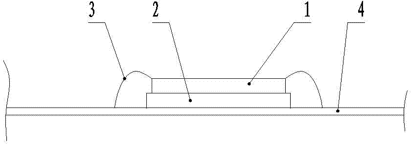
[0020] Example 1, such as figure 2 As shown, a flexible LED light source filament is improved on the basis of the existing LED light source. Through holes are made on the substrate for fixing the LED chip, and the LED chip is put into the hole to realize light emission from both sides. Specifically: P-N junction 1 and sapphire 2 are packaged together to form a single LED chip, the single LED chip is fixed on the substrate 4 by a mixture of phosphor powder and epoxy resin, and the two ends of the P-N junction are connected to the substrate 4 through gold wire 3 For electrical connection, the distance between the two ends of the P-N junction and the substrate 4 is also smaller than the existing distance, which can save the amount of gold wire 3, and the substrate 4 is designed with a fixing hole for fixing a single LED chip that can hold the LED chip , the fixing hole is a two-stage hole with a large upper part and a smaller one at the lower part. The large hole 43 is a counter...

Embodiment 2

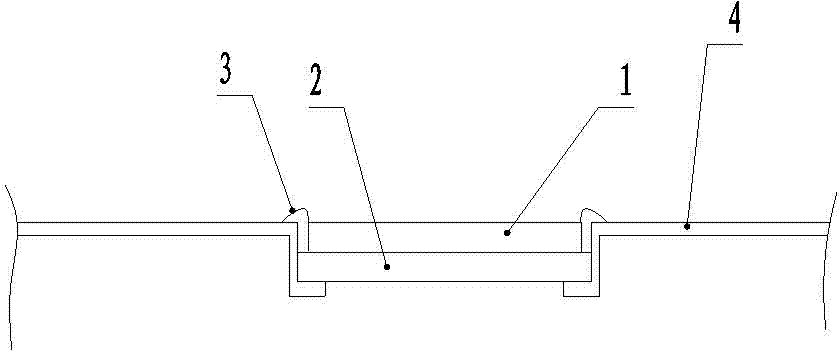
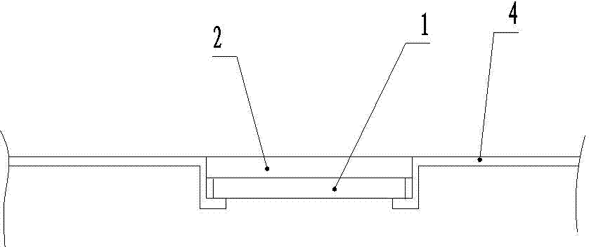
[0021] Example 2, such as image 3 , 4 As shown, it is improved on the basis of implementation 1. The substrate 4 is a copper plate with a thickness of 0.01-1mm and a width of 0.08-5mm. The surface is plated with silver, and the surface is etched with a conductive groove 41. It coincides with the center line of the fixing hole of the LED chip, and a plurality of fixing holes are evenly arranged, and each fixing hole is equipped with an LED chip, which can be cut according to the required brightness during use, and different numbers of LED chips can be selected. The inner diameter of the small hole 42 is smaller than the outer diameter of the P-N junction 1 in the LED chip. The P-N junction 1 of a single LED chip is downward, and the sapphire 2 is fixed in the fixing hole upward. The positive and negative poles of the P-N junction 1 are connected to the conductive groove 41. The conductive groove 41 is electrically connected.

Embodiment 3

[0022] Embodiment 3, on the basis of implementation 2, a transparent plate with a thickness of 0.01-1mm is selected as the substrate 4, the surface is shaped on a long groove, and a conductive sheet is fixed in the groove to form a conductive groove 41, so that the substrate does not block the light emission of the LED chip. , can maximize the light efficiency. All the other unmentioned parts are the same as the above example.


PUM


Abstract

The invention relates to LED (light-emitting diode) lamps and in particular relates to an LED light source filament. According to a flexible LED light source filament, a P-N junction and sapphire are packaged together to form a single LED wafer; the single LED wafer is fixed on a substrate through a mixture of fluorescent powder and epoxy resin; the design key points are that a fixing hole which can contain the LED wafer and is used for fixing the single LED wafer is formed in the substrate; the fixing hole is a two-section hole with larger top and smaller bottom; the larger hole is a counter bore; the smaller hole is a through hole; the inner diameter of the smaller hole is smaller than the outer diameter of the LED wafer. According to the flexible LED light source filament provided by the invention, the defect that a single face of LED is luminous is overcome, the luminous efficiency is improved, the temperature is reduced, the service life of the LED is prolonged, less heat is generated, the lamp is portable without a radiator, the defect that a lamp is heavy because of the required radiator in a traditional LED terminal lighting product is overcome, the LED light source is soft and can be optionally deformed and cut, and favorable conditions are provided for diversified large-luminous-angle development of terminal light source products.

Description

technical field [0001] The invention relates to LED lamps, in particular to LED light source filaments. Background technique [0002] A light-emitting diode is a solid-state semiconductor device that can convert electrical energy into visible light, and it can directly convert electricity into light. The heart of the LED is a wafer of light-emitting diodes. The entire wafer is encapsulated on a substrate of any structure by a mixture of phosphor powder and epoxy resin. One end is the negative pole, and the other end is connected to the positive pole of the power supply. For general lighting, people need more white light sources. And white light requires the cooperation of blue chip and yellow phosphor to achieve a series of white light that people need. In 1998, LEDs that emit white light were successfully developed. This kind of LED is made by packaging GaN chips and yttrium aluminum garnet (YAG), that is, packaging the P-N junction with sapphire. The power of a single L...

Claims


Application Information

Patent Timeline
Patent Type & Authority Applications(China)
IPC IPC(8): H01L33/48H01L33/54H01L33/64H01L33/62
CPCH01L33/005H01L33/483H01L33/62
Inventor 黄毅红
Owner 福州圆点光电技术有限公司
Why Eureka
Try Eureka