Slurry flow guide rod mechanism of solar silicon wafer fretsaw cutting machine

A technology for solar silicon wafers and saw cutting machines, which is applied to work accessories, fine work devices, stone processing equipment, etc. The effect of processing adaptability, saving slurry and improving work efficiency

Inactive Publication Date: 2014-01-08
HENGSHUI YINGLI NEW ENERGY
View PDF11 Cites 4 Cited by
  • Summary
  • Abstract
  • Description
  • Claims
  • Application Information

AI Technical Summary

Problems solved by technology

[0003] At present, the existing guide rods are fixed on the workbench by screws and cannot be moved, and the length of the guide rods is fixed, so the guide rods cannot be adjusted according to the wide band of the steel wire or the silicon ingot. Adjusting the horizontal position of the width of the wire saw reduces the practicality of the wire saw and wastes slurry

Method used


Image

  • Slurry flow guide rod mechanism of solar silicon wafer fretsaw cutting machine
  • Slurry flow guide rod mechanism of solar silicon wafer fretsaw cutting machine

Examples


Embodiment 1

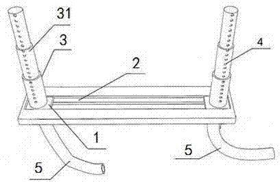
[0015] figure 1 As shown in the embodiment, a slurry guide rod mechanism for a solar silicon wafer wire saw cutting machine includes at least two guide rods, and is characterized in that each of the guide rods has a length telescopic mechanism.

[0016] Furthermore, the guide rod of the slurry guide rod mechanism of the solar silicon wafer wire saw cutting machine slides and cooperates with the slide rail 2 through the slider 1, and the slide rail 2 is perpendicular to the length direction of the guide rod.

[0017] To further explain this embodiment, the slurry guide rod mechanism of the current solar silicon wafer wire saw cutting machine is fixed on the workbench and cannot be stretched up and down and moved. For wire saw cutting machines, the length of silicon ingots is divided into many specifications. When cutting silicon wafers, it is necessary to adjust the appropriate winding width of the wire saw steel wire according to the length of the silicon ingot. The length o...

Embodiment 2

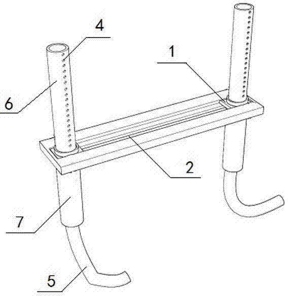
[0021] The difference between this embodiment and Embodiment 1 is: the slurry guide rod mechanism of the solar silicon wafer wire saw cutting machine, the length telescopic mechanism includes a fixed tube 6, a sliding tube 7, and a hose 5, and the fixed tube 6 The inner end and the hose 5 are socketed and fixed on the slider 1; the outer end of the sliding tube 7 is sealed; the lower part of the sliding tube 7 is inserted into the fixing tube 6, and is slidably matched and sealed with the sliding tube 7; A row of holes 4 is provided.

[0022] Further explanation of this embodiment: Different from Embodiment 1, the length telescopic mechanism of this embodiment is not formed by sliding and socketing a plurality of sleeve pipes 31 , but is composed of a sliding fit between the fixed pipe 6 and the sliding pipe 7 . The fixed pipe 6 is fixed on the slider 1, and the length of the guide rod is only adjusted by extending and withdrawing the slide pipe 7, thus avoiding the instabilit...


PUM


Abstract

The invention discloses a slurry flow guide rod mechanism of a solar silicon wafer fretsaw cutting machine, and relates to the technical field of solar silicon wafer cutting machines. The slurry flow guide rod mechanism at least comprises two flow guide rods, and the flow guide rods are respectively provided with a length telescopic mechanism. The flow guide rods of the slurry flow guide rod mechanism of the solar silicon wafer fretsaw cutting machine are in sliding fit with a sliding rail through sliding blocks, and the sliding rail is perpendicular to the length direction of the flow guide rods. The slurry flow guide rod mechanism has the advantages that through the length telescopic mechanisms, the sliding blocks and the sliding rail of the slurry flow guide rod mechanism of the solar silicon wafer fretsaw cutting machine, the length and the horizontal positions of the flow guide rods can be adjusted according to the width of a fretsaw and the width of a cut silicon ingot, slurry is saved, the processing adaptability of the solar silicon wafer fretsaw cutting machine is improved, and working efficiency is improved.

Description

technical field [0001] The present invention relates to the technical field of solar silicon slicer. Background technique [0002] During the production and processing of solar silicon wafers, steps such as polishing, chamfering, cutting, cleaning, and testing are required. In the cutting process of silicon wafers, the machine guide wheel drives the cutting wire during high-speed operation, so that the cutting fluid is sent to the cutting area by the cutting wire, and rubs against the silicon ingot during the high-speed operation of the cutting wire to complete the cutting process. In order to stabilize the flow of cutting fluid during silicon wafer cutting, so that the cutting fluid can be evenly spread on the cutting line, it is necessary to install a nozzle at the end of the cutting fluid pipe to control the flow direction of the cutting fluid. Install a guide at both ends of the nozzle The flow bar prevents the cutting fluid from shrinking together due to surface tensio...

Claims


Application Information

Patent Timeline
Patent Type & Authority Applications(China)
IPC IPC(8): B28D5/04B28D7/00
Inventor 任军海张利赵岩磊杜广宇
Owner HENGSHUI YINGLI NEW ENERGY
Why Eureka
Try Eureka