

Polarizing Plate and Liquid Crystal Display Device
- Summary
- Abstract
- Description
- Claims
- Application Information
AI Technical Summary
Benefits of technology
Problems solved by technology
Method used
Image

Examples
example 1
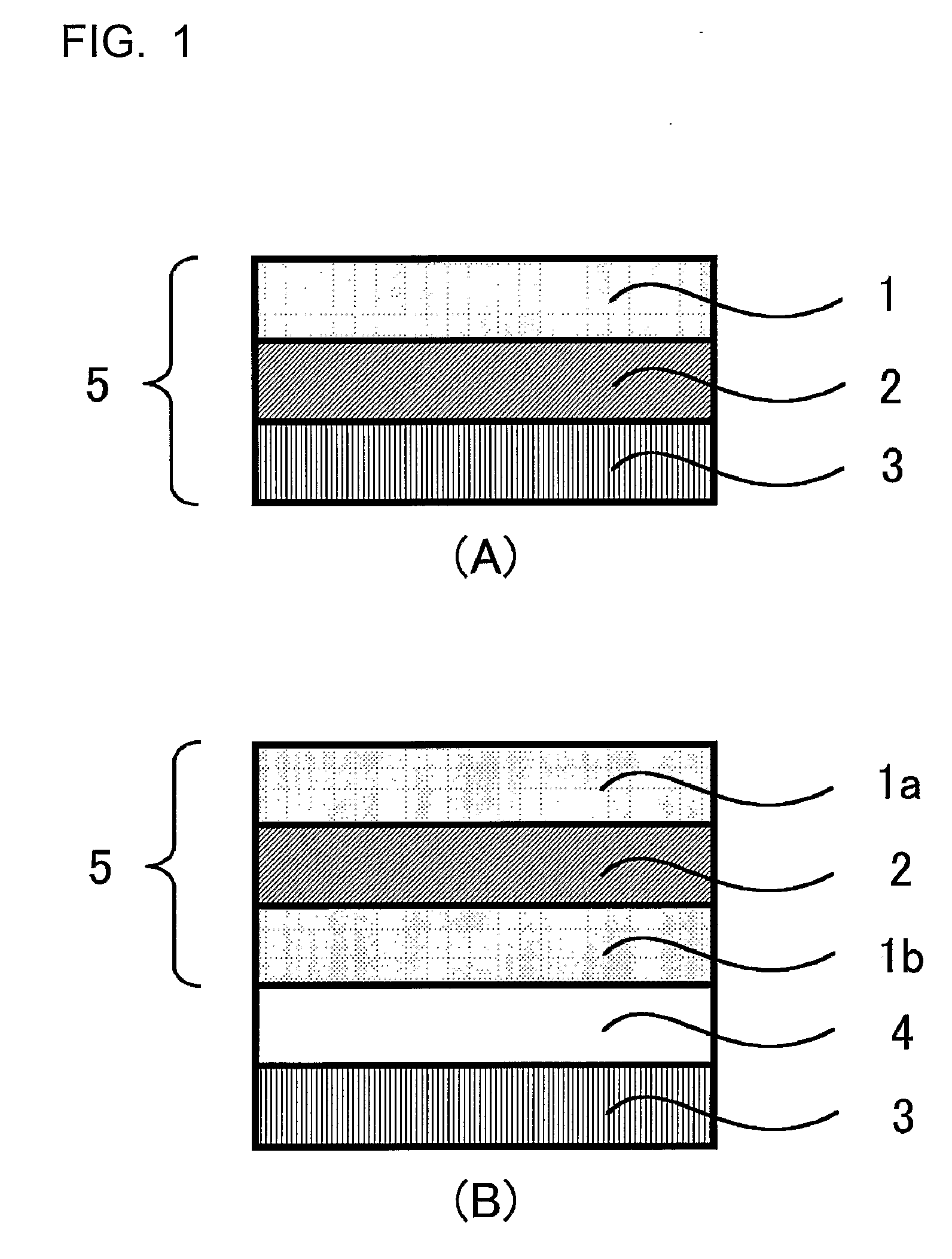
[0486]Both faces of the above-mentioned polarizer were coated with the above-mentioned adhesive solution, and the polarizing plate protective films A-1 and B-1 prepared above were laminated so as to sandwich the polarizer, dried, and cured in an oven at 40° C. for 72 hours to give a polarizing plate 1 having a total thickness of 178 μm. The transmittance of the polarizing plate thus obtained was 42%, and the degree of polarization was 99.9%.
Preparation of Polarizing Plates 2 to 10
example 9
Preparation and Evaluation of VA Liquid Crystal Display Device 1
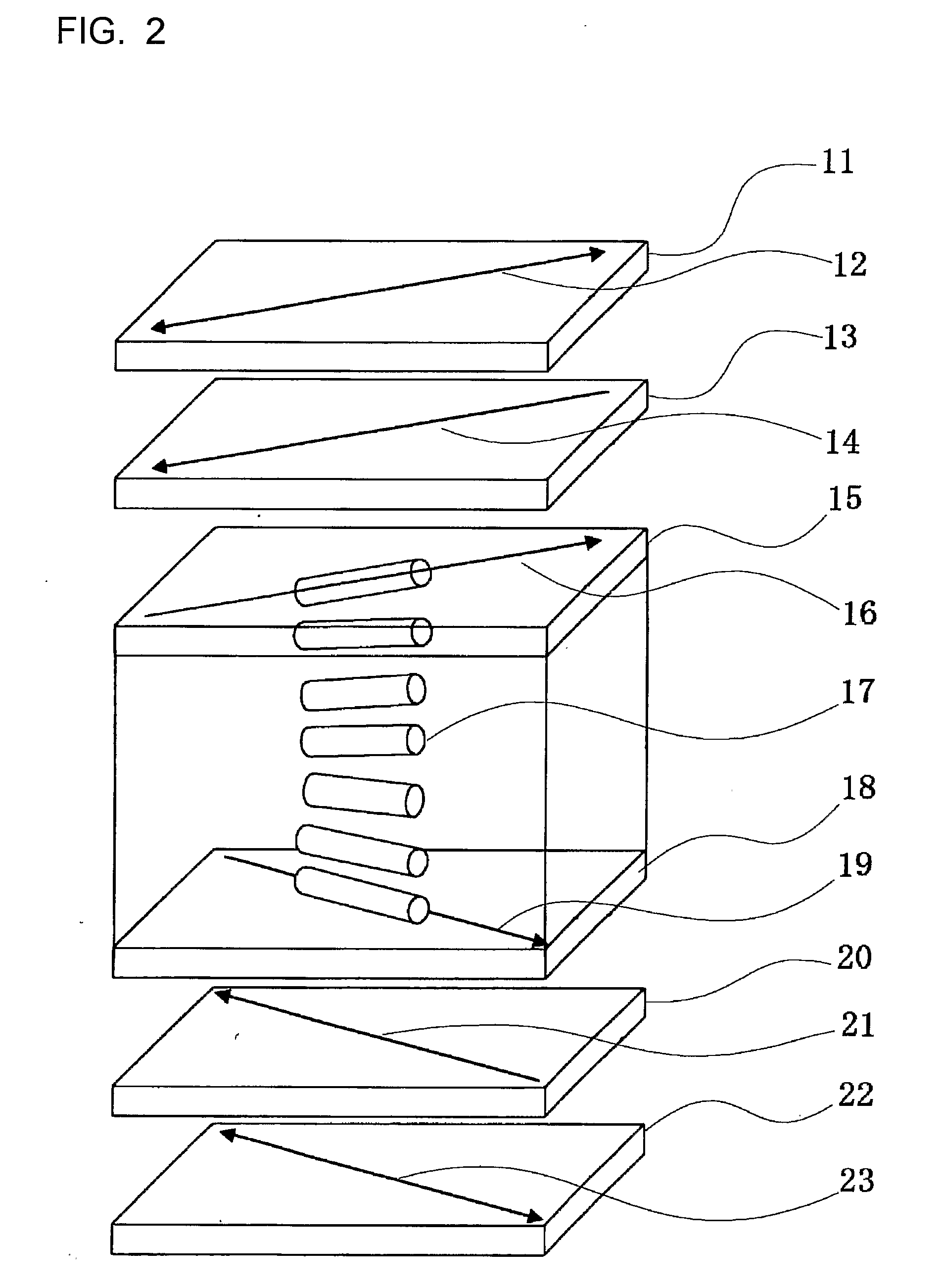
[0492]1 wt % of octadecyldimethylammonium chloride (coupling agent) was added to a 3 wt % aqueous solution of polyvinyl alcohol. This was applied on top of an ITO electrode-equipped glass substrate by spin coating, thermally treated at 160° C., and then subjected to a rubbing treatment to give a vertically aligned film. The rubbing treatment was carried out so that the directions were opposite for two glass substrates. The two glass substrates faced each other across a cell gap (d) of 5 μm. A liquid crystal compound (Δn: 0.08) containing an ester system and an ethane system as main components was poured into the cell gap to give a vertically aligned liquid crystal cell. The product of Δn and d was 400 nm.
[0493]After the polarizing plate 2 prepared above was conditioned in advance under temperature and humidity conditions of 25° C. and 60% RH, it was wrapped in a bag that had been subjected to a moisture-proofing treatme...
example 10
Preparation and Evaluation of VA Liquid Crystal Display Device 2
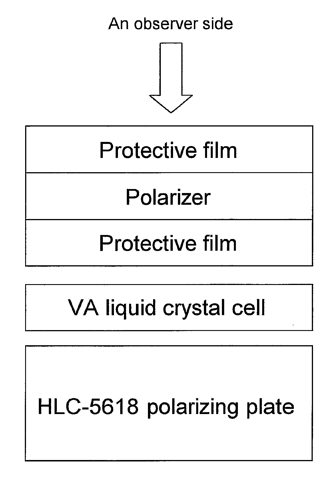
[0496]A liquid crystal display device of FIG. 3 was prepared. That is, going from the viewing direction (top), an upper side polarizing plate, a VA mode liquid crystal cell (an upper substrate, a liquid crystal layer, a lower substrate), and a lower side polarizing plate were laminated, and a backlight light source was arranged. In an example below, a commercial polarizing plate (HLC2-5618) was used as the upper side polarizing plate, and the polarizing plate of the present invention was used as the lower side polarizing plate.
[0497]A liquid crystal cell was prepared by setting a cell gap between substrates at 3.6 μm, pouring dropwise a liquid crystal material (‘MLC6608’, manufactured by Merck) having a negative anisotropic permittivity between the substrates, and sealing so as to form a liquid crystal layer between the substrates. The retardation of the liquid crystal layer (that is, the product Δn·d of a thickness d (...
PUM
| Property | Measurement | Unit |
|---|---|---|
| Temperature | aaaaa | aaaaa |
| Temperature | aaaaa | aaaaa |
| Relative humidity | aaaaa | aaaaa |
Abstract
Description
Claims
Application Information