
HCl recovery technique

A process and gas technology, which is applied in the field of recycling process in industrial production, can solve the problems of high energy consumption and large investment in equipment, and achieve the effects of wide application, reduced energy consumption, and saving equipment investment and maintenance

Active Publication Date: 2014-01-08
LIAOCHENG LUXI CHEM ENG DESIGN
View PDF5 Cites 13 Cited by
  • Summary
  • Abstract
  • Description
  • Claims
  • Application Information

AI Technical Summary

Problems solved by technology

The disadvantage of this process is high energy consumption and large investment in equipment

Method used


Image

  • HCl recovery technique

Examples


Embodiment 1

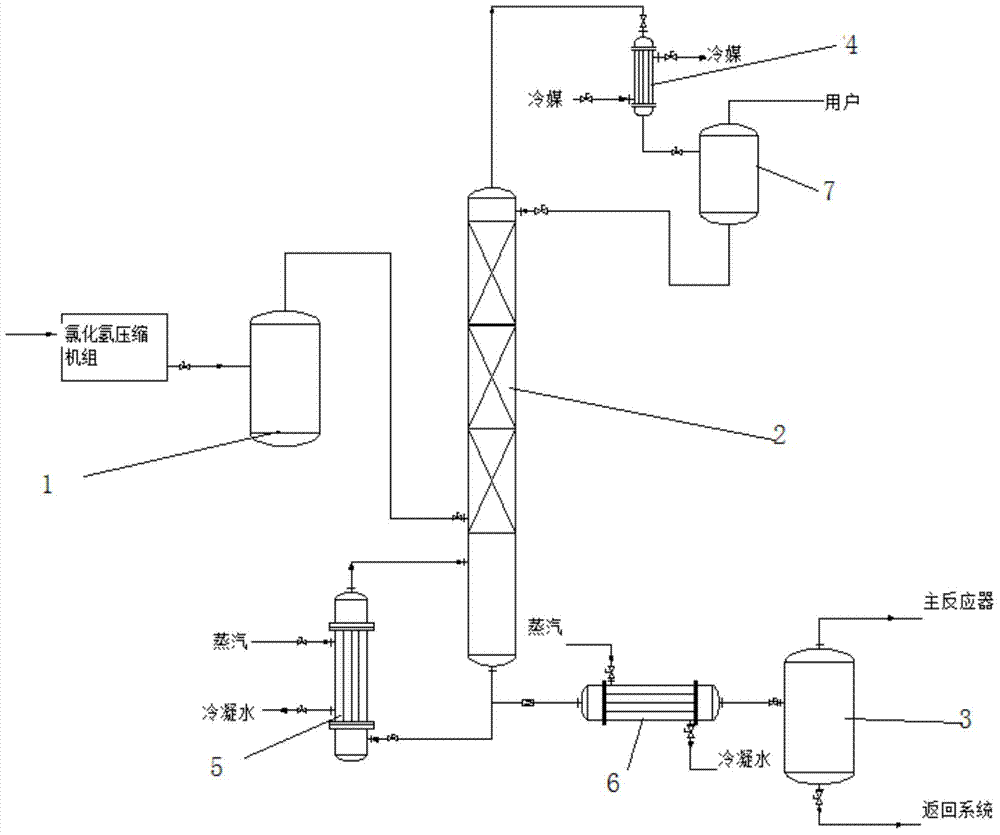
[0017] HCl mixed gas enters the compressor, and after three-stage compression, the pressure reaches 1.6MPa, and then it is sent to the HCL rectification tower after passing through the buffer tank, the feed rate is 3000Kg / h, and the temperature is 40°C. The reboiler at the bottom of the tower is heated to about 60°C with steam, and the output at the bottom of the tower is 490kg / h. The HCl gas is produced at the top of the tower, and the HCl gas produced at the top of the tower is condensed through the top condenser 4, the condensation temperature is -17°C, the output is 2510kg / h, and the cooling capacity consumption of the HCl pressurized rectification production process is 0.09MKal / h, heat consumption is 0.1MKal / h.

[0018] When using the original process for recovery, the cooling energy consumption of the HCl absorption and desorption process is 1.0MKal / h, and the heat consumption is 1.7MKal / h.

[0019] Compared with the recovery of the original process, the present inventi...


PUM


Abstract

The invention relates to a HCl recovery technique which comprises the following steps: pressurized HCl gas enters a HCl rectification tower with a heated tower bottom through a buffer tank; the gas HCl is recovered at the cooled tower top; chlorine gas and carbon tetrachloride at the bottom of the rectification tower are depressurized and heated and enters a flash tank to perform flash evaporation; and the chlorine gas is recovered at the top of the flash tank, and the carbon tetrachloride is recovered at the bottom. Compared with the original HCl absorption-desorption technique, the HCl pressurized rectification production technique provided by the invention saves the equipment investment and maintenance, lowers the energy consumption, and ensures the purity of the HCl gas.

Description

technical field [0001] The invention relates to a recovery process for industrial production, in particular to an HCl recovery process. Background technique [0002] In the tetrachlorethylene production unit, monochloromethane, chlorine and carbon tetrachloride generate tetrachlorethylene and hydrogen chloride in the main reactor, and after quenching and condensation, crude tetrachlorethylene and hydrogen chloride gas are obtained. Our company's existing process converts HCl The gas is passed into the hydrochloric acid absorber, absorbed by the dilute hydrochloric acid solution in the tail gas absorber, and then sent to the pressurized desorption tower for desorption. Existing HCl absorption and desorption process conditions: [0003] The gas from the three-stage gas-liquid separator enters the hydrochloric acid absorber and is absorbed by the dilute hydrochloric acid solution of the tail gas absorber, and 19% of the hydrochloric acid is sent to the top of the tail gas abso...

Claims


Application Information

Patent Timeline
Patent Type & Authority Applications(China)
IPC IPC(8): C01B7/07
Inventor 肖光袁甫荣管艳华田松杜景涛杜仰军
Owner LIAOCHENG LUXI CHEM ENG DESIGN
Learn More