Machining technology for electrified railway overhead line system metal die forging porcelain insulator lower steel cap

A technology for electrified railways and porcelain insulators, applied in circuits, insulators, electrical components, etc.

Active Publication Date: 2014-01-15
SHANDONG SHENLI RIGGING
View PDF5 Cites 7 Cited by
  • Summary
  • Abstract
  • Description
  • Claims
  • Application Information

AI Technical Summary

Problems solved by technology

Due to the unavoidable defects in the existing cast steel caps, the actual effective size of some steel caps is smaller than the design value, and the strength and other requirements cannot be met.

Method used


Image

  • Machining technology for electrified railway overhead line system metal die forging porcelain insulator lower steel cap

Examples


Embodiment Construction

[0027] The invention relates to a processing technology for the lower steel cap of the metal forged porcelain insulator of the electrified railway catenary, which is processed according to the following steps in sequence:

[0028] 1) Cut the Q235B bar material into a blank with a size of Φ70mm×125mm.

[0029] The preferred cutting method is: place the Q235B bars on the longitudinally extending non-powered horizontal conveying roller line, the front of the roller line is provided with a rear clamping mechanism and a front clamping mechanism for the bars to pass through, and the rear clamping mechanism and the front The clamping mechanism can switch between clamping and loosening the bar, and a direct-acting travel switch is provided in front of the front clamping mechanism. The saw blade of the electric circular saw is located between the front clamping mechanism and the direct-acting travel switch. The longitudinal distance between the saw blade and the direct-acting travel sw...


PUM

PropertyMeasurementUnit
thicknessaaaaaaaaaa
thicknessaaaaaaaaaa

Abstract

The invention provides a machining technology for an electrified railway overhead line system metal die forging porcelain insulator lower steel cap. The machining technology comprises the steps that a blank with the diameter being 70mm*125mm is cut, a ceramic fiber blanket wraps the blank to slow down the heat loss, upsetting is carried out on the heated blank, an oxide skin on the outer circular surface of a middle blank is removed through a steel brush after upsetting to improve the quality of a forge piece, die forging is carried out, a cylindrical part is forged into the circular cone cylindrical shape and then is forged into the cylindrical shape with the equal diameter, forging quality is good, forging efficiency is high, quenching is carried out on a finished forge piece, an oxide skin on the surface of the finished forge piece is removed through a grinding brush, a through hole and the inner wall of the cylindrical part are machined, the surface is processed, galvanization is carried out, and then machining of the lower steel cap is finished.

Description

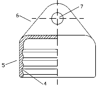
technical field [0001] The invention relates to the processing technology of the lower steel cap of the metal die forging porcelain insulator of the electrified railway catenary. Background technique [0002] The steel caps of porcelain insulators for electrified railway catenary include upper steel caps and lower steel caps, figure 1 The structure of the lower steel cap is shown, and the lower steel cap includes a cylindrical part 5, an ear part 6 and a connecting bottom plate between the cylindrical part and the ear part. The ear portion has a through hole 7 and the cylindrical portion has a corrugated inner wall 4 . The existing cast steel caps inevitably have defects inside, causing the actual effective size of some steel caps to be smaller than the design value, failing to meet the requirements of strength and the like. Contents of the invention [0003] The technical problem to be solved by the present invention is to provide a processing technology for the lo...

Claims


Application Information

Patent Timeline
Patent Type & Authority Applications(China)
IPC IPC(8): H01B19/00
Inventor 李成鑫王秀刚张体学仇恒臣廉明辉张来星
Owner SHANDONG SHENLI RIGGING
Why Eureka
Try Eureka