
Optical fiber communication system capable of regulating received optical power adaptively and running method thereof

An optical fiber communication system and self-adaptive adjustment technology, applied in the direction of electromagnetic receivers, etc., can solve the problems of restricting the application of analog signal optical fiber communication systems, increasing the loss of optical power transmission in optical transmission, and the low receiving optical power of optical receivers, etc., to avoid Bad effects, easy to implement, inexpensive effects

Inactive Publication Date: 2014-01-22
NO 34 RES INST OF CHINA ELECTRONICS TECH GRP
View PDF7 Cites 12 Cited by
  • Summary
  • Abstract
  • Description
  • Claims
  • Application Information

AI Technical Summary

Problems solved by technology

It is for this reason that the existing analog signal optical fiber communication system is only suitable for working in the specific optical cable length (transmission distance) of the system design, which greatly limits the application of analog signal optical fiber communication system
On the other hand, in the case of some optical fiber fusion splicing and optical interface connection of the transmission optical cable, the optical power loss of the optical transmission will also be increased due to human reasons, resulting in too small received optical power of the optical receiver, which affects the quality of the received signal

Method used


Image

  • Optical fiber communication system capable of regulating received optical power adaptively and running method thereof
  • Optical fiber communication system capable of regulating received optical power adaptively and running method thereof

Examples


Embodiment Construction

[0029] Embodiment of an optical fiber communication system for adaptively adjusting received optical power

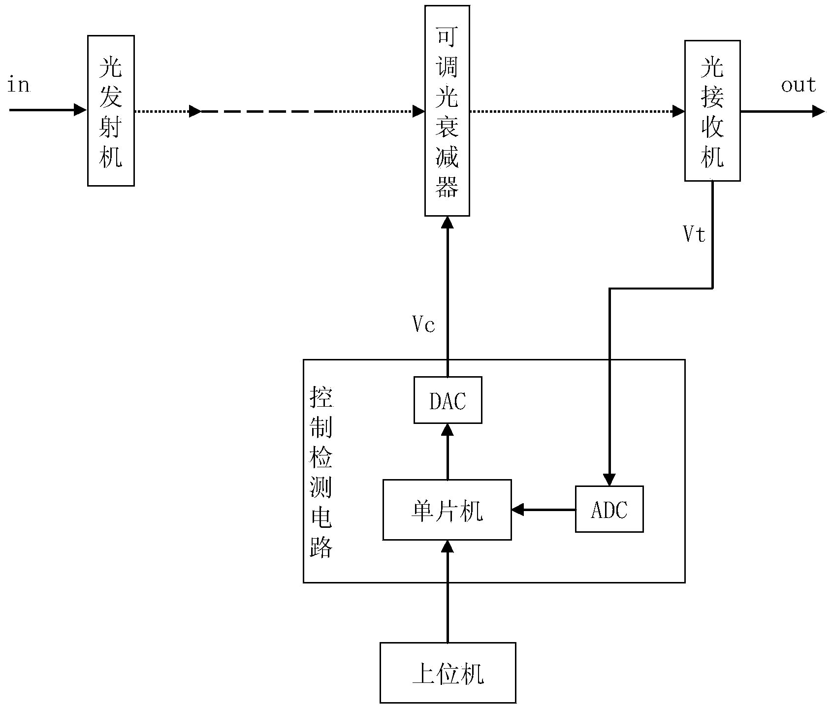
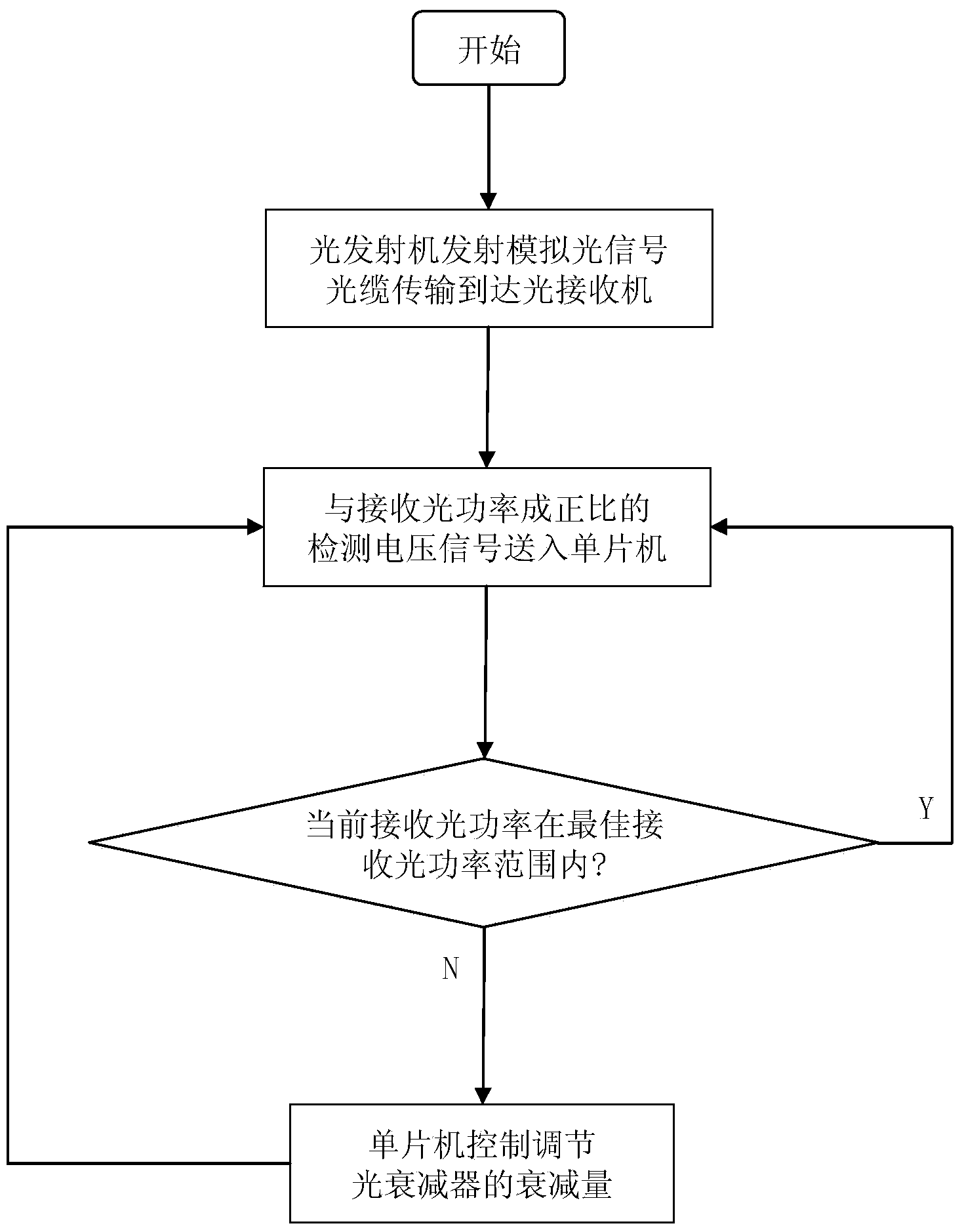
[0030] This example figure 1 Shown, comprise optical transmitter and optical receiver, optical transmitter and optical receiver are connected by optical cable, the output optical power of the simulated laser in this example optical transmitter is 18dBm, and working wavelength is 1550nm, the best of described optical receiver Received optical power is 1.5dBm ~ 2.5dBm. The attenuation of the optical signal on the transmission cable is 0.25dB per kilometer. In this case P out -P OM -P loss =2.5dB, then the maximum transmission distance in this example is: (18-2.5-2.5) / 0.25=52km. The transmission optical cable in this example is of any length within the range of 0-52km. This system can adaptively adjust the received optical power to the optimal received optical power of its optical receiver to ensure the good quality of optical fiber communication.

[0031] The optica...


PUM


Abstract

The invention provides an optical fiber communication system capable of regulating received optical power adaptively and a running method thereof. Analog optical signal power output by an optical transmitter is larger than the sum of an upper limit value of the optimum reception power range of an optical receiver and transmission attenuation amount, an analog optical signal enters an optical attenuator and then enters the optical receiver, sampling voltage of an optical detector in the optical receiver accesses a control detection circuit which is connected with the optical attenuator. The control detection circuit comprises a single chip microcomputer and an AD / DA conversion module. The running method of the system comprises the steps as follows: the optical signal of the optical transmitter enters the optical receiver through the optical attenuator; detection voltage value of an optical detector sample resistor of the optical receiver is sent to the single chip microcomputer; and the single chip microcomputer determines the current received optical power, continues to detect if the power is in the optimum reception optical power range, otherwise, determines the attenuation according to a difference, and controls and regulates the optical attenuator. The optical fiber communication system and the running method thereof regulate received optical power dynamically and adaptively to the optimum value, stabilize optical fiber communication, are suitable for different optical receiver, and easy to implement.

Description

technical field [0001] The invention relates to the technical field of electronic communication, in particular to an optical fiber communication system for adaptively adjusting received optical power and an operating method thereof. Background technique [0002] At present, as the amount of data in the communication system increases and the signal bandwidth becomes wider and wider, analog signal optical fiber communication, especially high-frequency analog signal optical fiber communication, is widely used. The existing analog optical fiber communication technology consists of an optical transmitter, an optical cable, and an optical receiver. Due to different transmission distances, different lengths of optical cables, and different losses in the transmission process, the optical power received by the receiver is different. At present, the best received optical power of most optical receivers is 2±0.5dBm, and the best received optical power of high-frequency optical receiver...

Claims


Application Information

Patent Timeline
Patent Type & Authority Applications(China)
IPC IPC(8): H04B10/60
Inventor 岑少忠席虹标黄锋锋吴见平陈国帅胡彬陈君洪熊平戬谢宝荣谢嘉威
Owner NO 34 RES INST OF CHINA ELECTRONICS TECH GRP
Features
  • Generate Ideas
  • Intellectual Property
  • Life Sciences
  • Materials
  • Tech Scout
  • Unparalleled Data Quality
  • Higher Quality Content
  • 60% Fewer Hallucinations
Learn More