Method for enabling PTFE (Polytetrafluoroethylene) or FEP (Fluorinated Ethylene Propylene) surface to have super-hydrophobic and underwater high reflective properties simultaneously

A PTFE, high reflective technology, applied in the direction of manufacturing tools, welding equipment, laser welding equipment, etc., to achieve the effect of good stability of surface properties

Active Publication Date: 2014-02-05
BEIJING UNIV OF TECH
View PDF4 Cites 19 Cited by
  • Summary
  • Abstract
  • Description
  • Claims
  • Application Information

AI Technical Summary

Problems solved by technology

However, there are no relevant literature reports on t

Method used


Image

  • Method for enabling PTFE (Polytetrafluoroethylene) or FEP (Fluorinated Ethylene Propylene) surface to have super-hydrophobic and underwater high reflective properties simultaneously
  • Method for enabling PTFE (Polytetrafluoroethylene) or FEP (Fluorinated Ethylene Propylene) surface to have super-hydrophobic and underwater high reflective properties simultaneously
  • Method for enabling PTFE (Polytetrafluoroethylene) or FEP (Fluorinated Ethylene Propylene) surface to have super-hydrophobic and underwater high reflective properties simultaneously

Examples


example 1

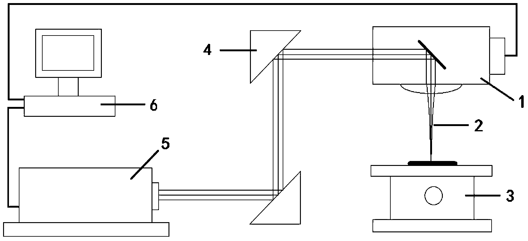
[0023] This example uses A three-band picosecond laser (1.064μm / 532nm / 355nm) was used as the processing light source. Its main technical parameters are as follows: wavelength output: 1.064μm / 532nm / 355nm; red light output: maximum pulse repetition frequency: 2MHz; maximum pulse energy: 80μJ; pulse width 10ps; beam quality M 2 =1.3; pulse energy stability 2%rms. Picosecond laser processing system such as figure 1 shown. The surface microstructure of the processed material was characterized by a laser confocal microscope (Olympus LEXT OLS3000), and the surface superhydrophobicity of the processed sample was measured by a contact angle meter (OCA20). The material used is British The 0.5mm thick polytetrafluoroethylene (PTFE) sheet produced by the company.

[0024] The specific operation steps are as follows: Adjust the optical path so that the indicating light passes through the galvanometer, passes through the converging lens, and projects onto the workbench. Fix the poly...

example 2

[0026] This example uses Picosecond lasers are used as processing light sources. 1064nm wavelength output: maximum pulse repetition frequency: 2MHz; maximum pulse energy: 80μJ; pulse width 10ps; beam quality M 2 =1.3; pulse energy stability 2%rms. Picosecond laser processing system such as figure 1 shown. The surface microstructure of the processed material was characterized by a laser confocal microscope (Olympus LEXT OLS3000), and the surface superhydrophobicity of the processed sample was measured by a contact angle meter (OCA20). The material used is British The 0.5mm thick fluorinated ethylene propylene resin (FEP) sheet produced by the company.

[0027] The specific operation steps are as follows: Adjust the optical path so that the indicating light passes through the galvanometer, passes through the converging lens, and projects onto the workbench. Fix the fluorinated ethylene propylene resin sheet on the workbench, and adjust the height of the workbench so that...


PUM


Abstract

A method for enabling a PTFE (Polytetrafluoroethylene) or FEP (Fluorinated Ethylene Propylene) surface to have super-hydrophobic and underwater high reflective properties simultaneously belongs to the laser machining field. According to the method, a 1064 nm picosecond laser micro-machining system is utilized to machine a one-dimensional or a dimensional trench array with a 25 mum seam width in PTFE and FEP surfaces so as to enable the surfaces to have super-hydrophobicity; if a prepared super-hydrophobic sample is completely immersed in water, a super-hydrophobic surface may take on a metallic luster high reflective surface. The method comprises the operating steps of: adjusting a picosecond laser light path, drawing a machining path by utilizing professional software, adjusting a picosecond laser output power based on a machining requirement, outputting picosecond pulse laser for machining when the laser power meets the requirement, achieving a super-hydrophobic requirement without subsequent cleaning after the machining is finished, and immersing the finished product in water to make a metal-like high reflective surface appear directly.

Description

technical field [0001] The invention relates to a method for obtaining a superhydrophobic and underwater highly reflective surface by using a 1064nm picosecond laser processing system to micro-process the surface of PTFE and FEP materials. Background technique [0002] The self-cleaning, anti-icing and anti-coagulation properties of superhydrophobic materials make them play an important role in national defense, industry, medicine and daily life. According to the wettability model, the prerequisite for obtaining a superhydrophobic surface is to reduce the free energy of the solid surface and increase the roughness of the solid surface. However, polytetrafluoroethylene and fluorinated ethylene propylene resins have extremely low fluorine-carbon chain intermolecular forces, and have extremely low surface free energy, and their surface free energy is much smaller than that of water. Therefore, if the microscopic morphology conforming to the infiltration model can be processed ...

Claims


Application Information

Patent Timeline
IPC IPC(8): B23K26/36
CPCB23K26/0006B23K26/355B23K2103/42
Inventor 蒋毅坚曹文深赵艳吴燕
Owner BEIJING UNIV OF TECH
Why Eureka
Try Eureka