Polycrystalline silicon ingot furnace

A polysilicon ingot casting furnace and furnace body technology, applied in the direction of polycrystalline material growth, crystal growth, single crystal growth, etc., can solve the problems of high viscosity of silicon liquid, uneven distribution of liquid phase components, short free volatilization time, etc., to achieve Uniform distribution of resistivity, uniform distribution of liquid phase components, and the effect of ensuring quality and performance

Active Publication Date: 2014-02-05
LESHAN TOPRAYCELL
View PDF4 Cites 23 Cited by
  • Summary
  • Abstract
  • Description
  • Claims
  • Application Information

AI Technical Summary

Problems solved by technology

However, too long time after the silicon material is melted will lead to the destruction of the silicon nitride coating inside the crucible. Therefore, after the silicon material is melted, it will start to cool down to the crystal growth temperature. The free volatilization time is short, and most of the volatile impurities Before volatilization, it enters the crystal growth stage, and the impurities are solidified in the silicon ingot. At this time, the viscosity of the silicon liquid is relatively high, and the non-volatile impurities and volatile impurities are not fully diffused in the silicon solution. Uneven distribution leads to impurity-enriched areas in the solidified ingot, resulting in uneven distribution of the resistivity of the ingot, which seriously affects the quality and performance of the ingot itself

Method used


Image

  • Polycrystalline silicon ingot furnace
  • Polycrystalline silicon ingot furnace
  • Polycrystalline silicon ingot furnace

Examples


Embodiment Construction

[0033] The present invention will be further described below in conjunction with the accompanying drawings.

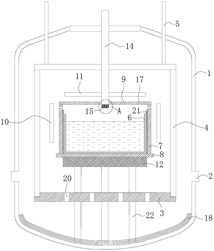
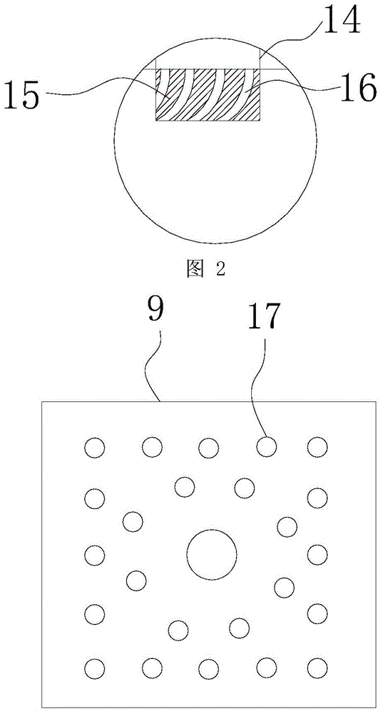
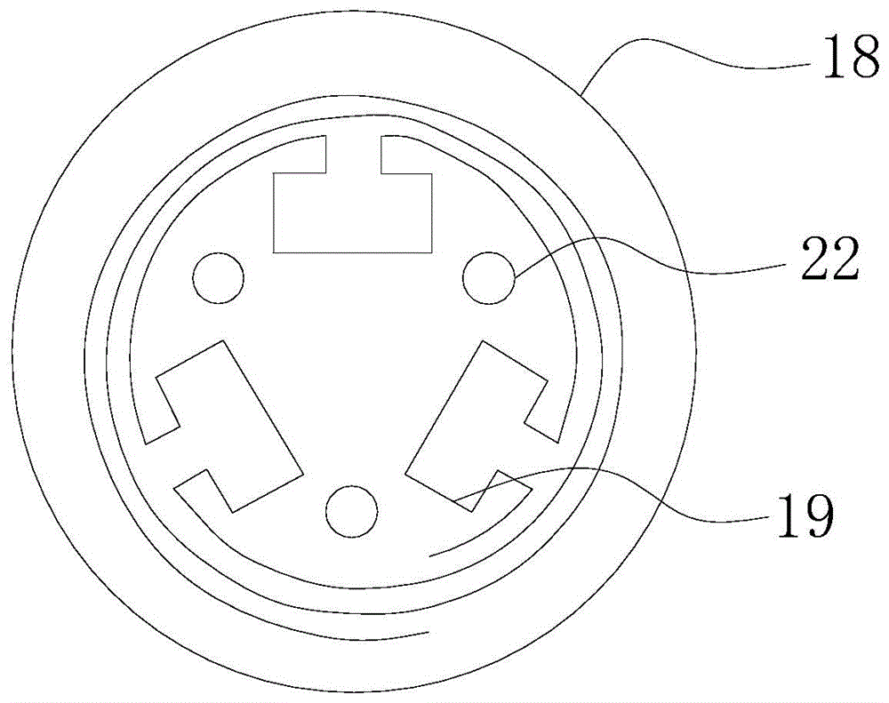
[0034] like Figures 1 to 5As shown, the polysilicon ingot casting furnace includes a furnace body 1, and the furnace body 1 is provided with an air extraction hole 2, and the furnace body 1 is provided with a lower heat preservation board 3 and a heat preservation cover 4, and the heat preservation cover 4 is placed on the lower heat preservation board 3, the thermal insulation cover 4 and the lower support thermal insulation board 3 together form a thermal insulation cage, the thermal insulation cover 4 is connected with a lifting rod 5 that can move the thermal insulation cover 4 up and down, and a crucible 6 is arranged in the thermal insulation cage , crucible guard plate 7, graphite base plate 8, graphite cover plate 9, side heater 10, top heater 11, heat exchange platform 12, described graphite base plate 8 is placed on the heat exchange platform 12, and crucibl...


PUM

PropertyMeasurementUnit
thicknessaaaaaaaaaa
thicknessaaaaaaaaaa

Abstract

The invention discloses a polycrystalline silicon ingot furnace which can enable the resistivity of a cast ingot to be distributed uniformly. A stop block for sealing a gas outlet is arranged at the gas outlet of a gas inlet pipe of the polycrystalline silicon ingot furnace, a plurality of spiral holes with the same helical direction are formed in the stop block, the plurality of the spiral holes are arranged around the central axis of the gas inlet pipe, inlets of the spiral holes are positioned on the upper surface of the stop block, and outlets of the spiral holes are positioned on the lower surface of the stop block. After argon gas passes through the spiral holes, the gas outlet way of the argon gas is changed from original direct blowing to rotating gas outlet, and the argon gas which is sprayed out of the spiral holes in a rotating manner can drive a silicon solution in a crucible to rotate, so that impurities contained in the silicon solution can be fully diffused in the silicon solution, the distribution of liquid-phase components is uniform, and the uniform distribution of the resistivity of the cast ingot is ensured; furthermore, the stirring of the silicon solution in the crucible can enable the volatile impurities contained in the silicon solution to be volatilized as soon as possible so as to ensure the quality and performance of the cast ingot. The polycrystalline silicon ingot furnace is suitable for popularization and application in the field of polycrystalline silicon production equipment.

Description

technical field [0001] The invention relates to the field of polysilicon production equipment, in particular to a polysilicon ingot casting furnace. Background technique [0002] Solar cells can convert light energy into electrical energy, which is a key point in the development of a modern energy-saving society. According to different substrate materials, existing solar cells are divided into polycrystalline silicon solar cells, monocrystalline silicon solar cells and quasi-monocrystalline silicon solar cells. Among them, the conversion efficiency of monocrystalline silicon solar cells is high, but the production cost is also high. The conversion efficiency of polycrystalline silicon solar cells is 1%-2% lower than that of monocrystalline silicon solar cells, but its production cost is also low. The battery is a battery between a monocrystalline silicon battery and a polycrystalline silicon solar battery. Comprehensive consideration, the current solar cells on the market ...

Claims


Application Information

Patent Timeline
Patent Type & Authority Applications(China)
IPC IPC(8): C30B28/06C30B29/06
Inventor 陈五奎李军马涛樊茂德徐文州冯加保
Owner LESHAN TOPRAYCELL
Why Eureka
Try Eureka