Method and system for supplying fuel to high-pressure natural gas injection engine

A fuel supply system and natural gas technology, applied in the direction of charging system, engine components, engine control, etc., can solve the problems of complex device configuration and low efficiency, and achieve the effects of reducing thermal stress, reducing thermal load, and reducing size

Pending Publication Date: 2014-02-05
DAEWOO SHIPBUILDING & MARINE ENG CO LTD
View PDF14 Cites 29 Cited by
  • Summary
  • Abstract
  • Description
  • Claims
  • Application Information

AI Technical Summary

Problems solved by technology

Nitrogen inverse Brayton cycle for offshore LNG liquefaction plant is relatively simple in terms of plant configuration and thus beneficial for constrained ships or offshore installations, but has low efficiency
The mixed refrigerant Joule-Thomson refrigeration cycle used in onshore LNG liquefaction equipment has relatively high efficiency, but the device configuration is complicated because it needs to be used to separate the mixed refrigerant when the characteristics of the mixed refrigerant cause the coexistence of gaseous and liquid states the separator

Method used


Image

  • Method and system for supplying fuel to high-pressure natural gas injection engine
  • Method and system for supplying fuel to high-pressure natural gas injection engine
  • Method and system for supplying fuel to high-pressure natural gas injection engine

Examples


no. 1 example )

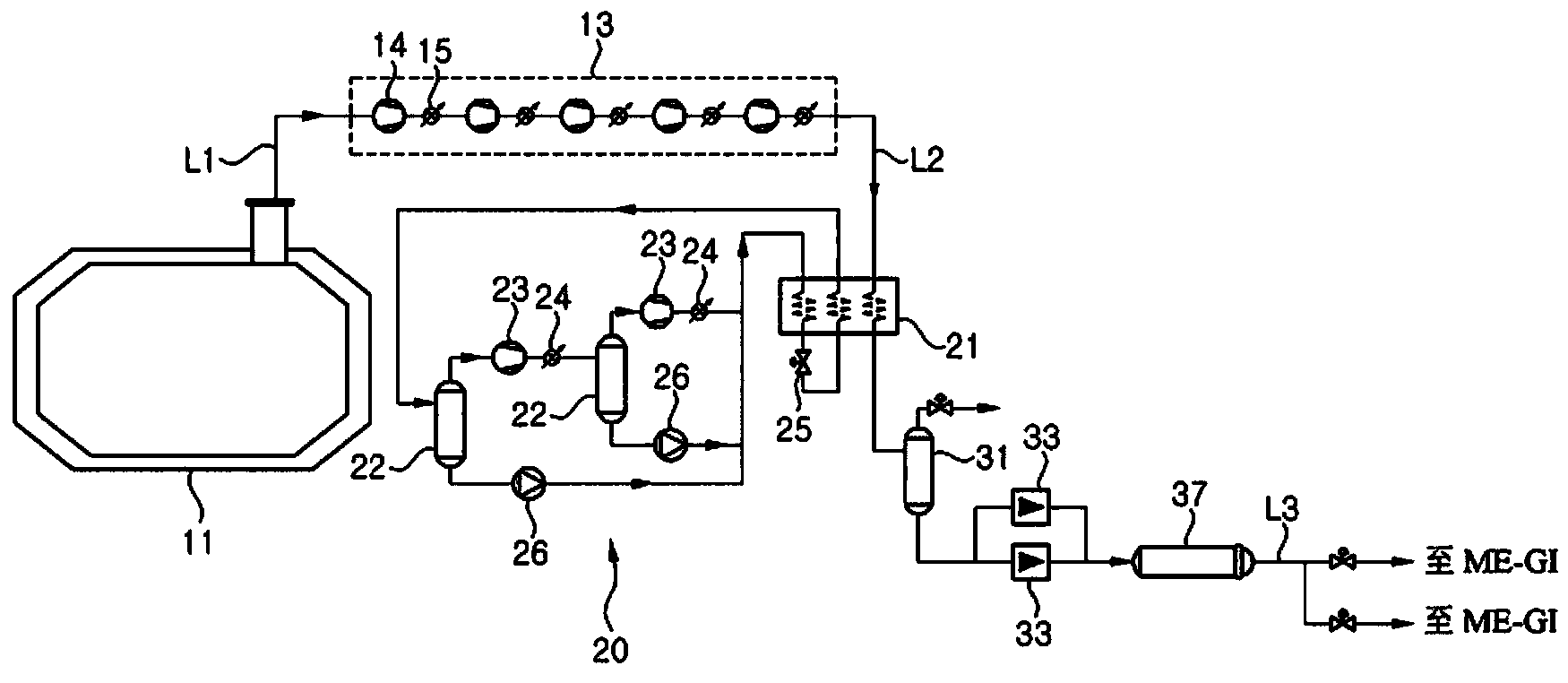
[0080] Figure 3a is a configuration diagram illustrating a fuel supply system for an ocean structure such as an LNG carrier having a high-pressure natural gas injection engine such as an ME-GI engine according to a first embodiment of the present invention. Figure 3a An example is illustrated in which the fuel supply system for a high-pressure natural gas injection engine according to the present invention is applied to an LNG carrier equipped with an ME-GI engine capable of using natural gas as fuel. However, the fuel supply system for a high-pressure natural gas injection engine according to the present invention can also be applied to any kind of marine structure equipped with a liquefied gas storage tank. Examples of marine structures may include vessels such as LNG carriers and LNG RVs, and offshore units such as LNG FPSOs and LNG FSRUs.

[0081] According to the fuel supply system for a marine structure having a high-pressure natural gas injection engine according to ...

no. 2 example )

[0124] Figure 7a is a configuration diagram illustrating a fuel supply system for a marine structure having a high-pressure natural gas injection engine (eg, ME-GI engine) according to a second embodiment of the present invention. Figure 7a The second embodiment shown in is different from the first embodiment only in that the fuel supply system is fed from the high-pressure pump 33 to the high-pressure gasifier before the reliquefaction unit reliquefies the BOG compressed to medium pressure The LNG in 37 is heat exchanged to preheat the compressed BOG. Therefore, the following description will focus on the differences from the first embodiment.

[0125] Such as Figure 7a As shown, the liquefied BOG compressed to a high pressure by the high-pressure pump 33 exchanges heat with the BOG supplied to the reliquefaction device 20 in the heat exchanger 35 before being supplied to the high-pressure vaporizer 37 . Since the temperature of the liquefied BOG supplied to the high-pr...

no. 3 example )

[0133] Figure 8a is a configuration diagram illustrating a fuel supply system for a marine structure having a high-pressure natural gas injection engine (eg, ME-GI engine) according to a third embodiment of the present invention. Figure 8a The third embodiment shown differs from the first embodiment only in that the fuel supply system preheats the BOG prior to compression. Therefore, the following description will focus on the differences from the first embodiment.

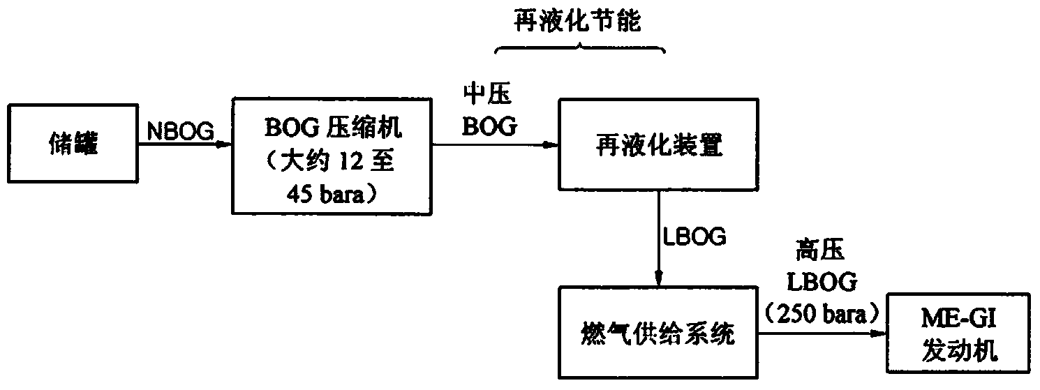
[0134] Such as Figure 8a As shown, in the fuel supply system for a marine structure having a high-pressure natural gas injection engine according to the second embodiment of the present invention, natural boil-off gas (natural boil-off gas, NBOG) is compressed by the BOG compression unit 13 to a medium pressure of about 12 to 45 bara. The compressed BOG is supplied to a BOG preheater 41 installed on the upstream side of the BOG compression unit 13 before being supplied into the reliquefaction device 20 . Th...


PUM


Abstract

Provided is a fuel supply system for a marine structure using a high-pressure natural gas injection engine, for example, an ME-GI engine, in which boil-off gas generated in an LNG storage tank is compressed to a medium pressure, reliquefied, compressed to a high pressure, gasified, and then supplied to the high-pressure natural gas injection engine. The fuel supply system for a high-pressure natural gas injection engine includes: a boil-off gas (BOG) compression unit configured to receive and compress BOG generated in a storage tank storing a liquefied gas; a reliquefaction apparatus configured to receive and liquefy the BOG compressed by the BOG compression unit; a buffer tank configured to receive the liquefied BOG from the reliquefaction apparatus and separate the reliquefied BOG into a gaseous component and a liquid component; a high-pressure pump configured to receive the liquid component from the buffer tank and compress the liquid component; and a high-pressure gasifier configured to gasify the liquid component compressed by the high-pressure pump and supply the gasified liquid component to the high-pressure natural gas injection engine. The liquid component supplied from the buffer tank to the high-pressure pump has a pressure of 12 to 45 bara (absolute pressure).

Description

technical field [0001] The present invention relates to a fuel supply system and method for a high-pressure natural gas injection engine, and more particularly, to a fuel supply system and method for a marine structure using a high-pressure natural gas injection engine method, for example, a MAN Electronic-Gas Injection (ME-GI) engine in which the boil-off gas (Boil Off Gas) generated in a liquefied natural gas (LNG) storage tank (storage tank) , BOG) is compressed to medium pressure, reliquefied, compressed to high pressure, gasified, and then fed into a high-pressure natural gas injection engine. Background technique [0002] Recently, consumption of natural gas such as liquefied natural gas (LNG) or liquefied petroleum gas (LPG) has rapidly increased around the world. Liquefied gas is transported in gaseous state through gas pipelines on land or at sea, or transported to distant points of consumption when it is stored in liquid state in a liquefied gas carrier. Liquefie...

Claims


Application Information

Patent Timeline
Patent Type & Authority Applications(China)
IPC IPC(8): F02M21/02F02M25/08F02M31/20
CPCF02M21/0215Y02T10/32F02D19/0605F02M21/0245Y02T10/36F02M21/0287Y02T10/30F17C7/04
Inventor 郑承教李正汉郑济宪李成俊申铉俊崔东圭
Owner DAEWOO SHIPBUILDING & MARINE ENG CO LTD
Why Eureka
Try Eureka